Electrical Symbols — Logic Gate Diagram

Mind Mapping Software
Circuits and Logic Diagram Software

Electrical Symbols, Electrical Diagram Symbols

Venn Diagram Examples for Problem Solving. Venn Diagram as a Truth Table

Basic Flowchart Symbols and Meaning


Electrical Symbols — Resistors

Diagrams Mean Nothing

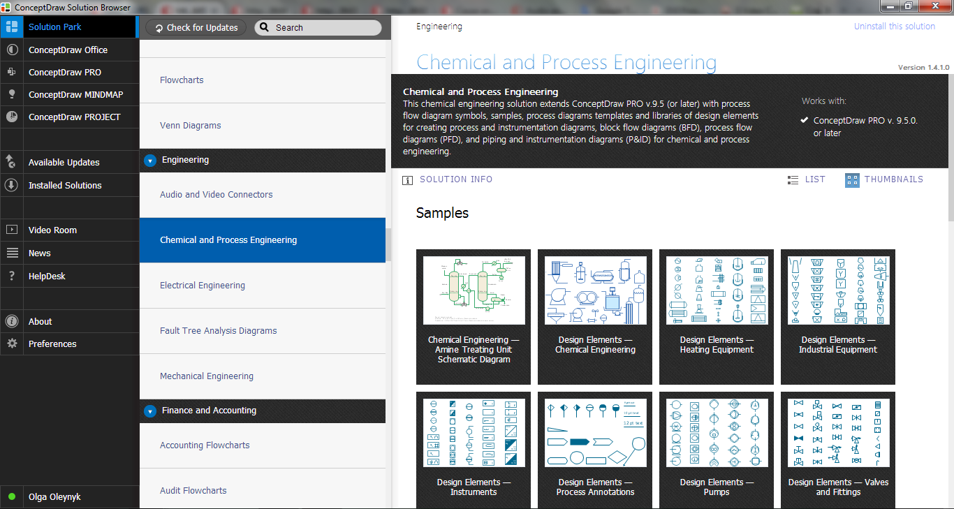
 Electrical Engineering
This solution extends ConceptDraw DIAGRAM.9.5 (or later) with electrical engineering samples, electrical schematic symbols, electrical diagram symbols, templates and libraries of design elements, to help you design electrical schematics, digital and analog
Process Flow Diagram Symbols
- Electrical Engineering | How To Draw Logic Gate In Ms Word
- Logic gate diagram - Template | Engineering | Templates Logic Gates
- How To Create Electrical Diagram In Microsoft Office
- How to Add a Bubble Diagram to MS Word | Entity-Relationship ...
- How to Insert a Mind Map into Microsoft Word Document | How to ...
- Pneumatic Symbols For Word
- How to Add a Block Diagram to a MS Word ™ Document Using ...
- How to Add a Floor Plan to a MS Word Document Using ...
- How to Add a Flowchart to a MS Word Document Using ...
- How to Insert a Mind Map into Microsoft Word Document | Concept ...