"The symbols and conventions used in welding documentation are specified in national and international standards such as ISO 2553 Welded, brazed and soldered joints -- Symbolic representation on drawings and ISO 4063 Welding and allied processes -- Nomenclature of processes and reference numbers. The US standard symbols are outlined by the American National Standards Institute and the American Welding Society and are noted as "ANSI/ AWS".
In engineering drawings, each weld is conventionally identified by an arrow which points to the joint to be welded. The arrow is annotated with letters, numbers and symbols which indicate the exact specification of the weld. In complex applications, such as those involving alloys other than mild steel, more information may be called for than can comfortably be indicated using the symbols alone. Annotations are used in these cases." [Symbols and conventions used in welding documentation. Wikipedia]
The example chart "Elements of welding symbol" is redesigned using the ConceptDraw PRO diagramming and vector drawing software from the Wikipedia file: Elements of a welding symbol.PNG.
[en.wikipedia.org/ wiki/ File:Elements_ of_ a_ welding_ symbol.PNG]
The diagram example "Elements location of a welding symbol" is contained in the Mechanical Engineering solution from the Engineering area of ConceptDraw Solution Park.
Welding joint symbol chart

Entity Relationship Diagram Symbols

Flowchart design. Flowchart symbols, shapes, stencils and icons


 Reflected Ceiling Plans
Reflected Ceiling Plans solution extends greatly the ConceptDraw DIAGRAM functionality with samples, templates and libraries of design elements for displaying the ceiling ideas for living room, bedroom, classroom, office, shop, restaurant, and many other premises. It is an effective tool for architects, designers, builders, electricians, and other building-related people to represent their ceiling design ideas and create Reflected Ceiling plan or Reflective Ceiling plan, showing the location of light fixtures, lighting panels, drywall or t-bar ceiling patterns, HVAC grilles or diffusers that may be suspended from the ceiling. Being professional-looking and vivid, these plans perfectly reflect your ceiling ideas and can be presented to the client, in reports, in presentations, on discussions with colleagues, or successfully published in modern print or web editions.
Electrical Symbols, Electrical Diagram Symbols

The vector stencils library "Map symbols" contains 10 spatial infographics symbols.
Use these signs and pictograms for drawing road and transit maps in the ConceptDraw PRO diagramming and vector drawing software extended with the Spatial Infographics solution from the area "What is Infographics" of ConceptDraw Solution Park.
Use these signs and pictograms for drawing road and transit maps in the ConceptDraw PRO diagramming and vector drawing software extended with the Spatial Infographics solution from the area "What is Infographics" of ConceptDraw Solution Park.
Windrose

North arrow
North arrow
Callout

Callout

Location

Direction Right

Direction Left

Direction Up

Direction Down

How To use House Electrical Plan Software


The vector stencils library "Map symbols" contains 10 spatial infographics symbols.
Use these signs and pictograms for drawing road and transit maps in the ConceptDraw PRO diagramming and vector drawing software extended with the Spatial Infographics solution from the area "What is Infographics" of ConceptDraw Solution Park.
Use these signs and pictograms for drawing road and transit maps in the ConceptDraw PRO diagramming and vector drawing software extended with the Spatial Infographics solution from the area "What is Infographics" of ConceptDraw Solution Park.
Windrose
North arrow
North arrow
Callout
Callout
Location
Direction Right
Direction Left
Direction Up
Direction Down
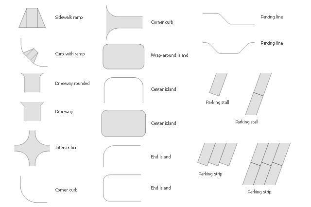
The vector stencils library Parking and roads contains 18 symbols of parking lots and strips, parking spaces, driveways, street junctions, and interchanges for parking facilities, on-street and off-street parking, and traffic management.
"A parking space is a location that is designated for parking, either paved or unpaved.
Parking spaces can be in a parking garage, in a parking lot or on a city street. It is usually designated by a white-paint-on-tar rectangle indicated by three lines at the top, left and right of the designated area. The automobile fits inside the space, either by parallel parking, perpendicular parking or angled parking." [Parking space. Wikipedia]
Use the design elements library Parking and roads to draw residential and commercial landscape design, parks planning, yard layouts, plat maps, outdoor recreational facilities, and irrigation systems using the ConceptDraw PRO diagramming and vector drawing software.
The shapes library Parking and roads is contained in the Site Plans solution from the Building Plans area of ConceptDraw Solution Park.
Building Drawing. Design Element Site Plan


- Which Type Of Warehouse Is Suitable For Storage Of White Goods
- Flowchart design. Flowchart symbols , shapes, stencils and icons ...
- Business feedback loop | U.S. Medicare spending per capita ...
- Flowchart design. Flowchart symbols , shapes, stencils and icons ...
- Storage Of White Goods In A Warehouse
- Elements location of a welding symbol | Spatial infographics Design ...
- Elements location of a welding symbol | Sales arrows - Vector ...
- Elements location of a welding symbol | Elements location of a ...
- Triangle Back Icon Png White
- Map symbols - Vector stencils library | Design elements - Location ...