"In computer networks, networked computing devices pass data to each other along data connections. The connections (network links) between nodes are established using either cable media or wireless media. ...
Network computer devices that originate, route and terminate the data are called network nodes. Nodes can include hosts such as personal computers, phones, servers as well as networking hardware. ...
Network links.
The communication media used to link devices to form a computer network include electrical cable (HomePNA, power line communication, G.hn), optical fiber (fiber-optic communication), and radio waves (wireless networking). In the OSI model, these are defined at layers 1 and 2 - the physical layer and the data link layer.
A widely adopted family of communication media used in local area network (LAN) technology is collectively known as Ethernet. The media and protocol standards that enable communication between networked devices over Ethernet are defined by IEEE 802.3. Ethernet transmit data over both copper and fiber cables. Wireless LAN standards (e.g. those defined by IEEE 802.11) use radio waves, or others use infrared signals as a transmission medium. Power line communication uses a building's power cabling to transmit data. ...
Network nodes.
Apart from the physical communications media described above, networks comprise additional basic system building blocks, such as network interface controller (NICs), repeaters, hubs, bridges, switches, routers, modems, and firewalls." [Computer network. Wikipedia]
The network equipment and cabling layout floorplan template for the ConceptDraw PRO diagramming and vector drawing software is included in the Network Layout Floor Plans solution from the Computer and Networks area of ConceptDraw Solution Park.
LAN equipment and cabling layout floorplan template

The vector stencils library "Network layout floorplan" contain 34 symbol icons for drawing computer network floor plans and communication equipment and cabling layouts.
"Networking hardware may also be known as network equipment or computer networking devices. Units which are the last receiver or generate data are called hosts or data terminal equipment.
All these terms refer to devices facilitating the use of a computer network. Specifically, they mediate data in a computer network. ...
Typically, networking hardware includes gateways, routers, network bridges, switches, hubs, and repeaters. But it also includes hybrid network devices such as multilayer switches, protocol converters, bridge routers, proxy servers, firewalls, network address translators, multiplexers, network interface controllers, wireless network interface controllers, modems, ISDN terminal adapters, line drivers, wireless access points, networking cables and other related hardware.
The most common kind of networking hardware today is a copper-based Ethernet adapter because of its standard inclusion on most modern computer systems. Wireless networking has, however, become increasingly popular, especially for portable and handheld devices.
Other hardware prevalent in computer networking includes data center equipment (such as file servers, database servers and storage areas), network services (such as DNS, DHCP, email, etc.) as well as devices which assure content delivery." [Networking hardware. Wikipedia]
The shapes example "Design elements - Network layout floorplan" was created using the ConceptDraw PRO diagramming and vector drawing software extended with the Network Layout Floor Plans solution from the Computer and Networks area of ConceptDraw Solution Park.
Network layout floor plan symbols

Network Diagramming Software for Design Computer and Network Diagrams
_Win_Mac.png "Network Diagramming Software, Design Elements — Computer and Network (Windows, Macintosh)")

 Office Layout Plans
Office layouts and office plans are a special category of building plans and are often an obligatory requirement for precise and correct construction, design and exploitation office premises and business buildings. Designers and architects strive to make office plans and office floor plans simple and accurate, but at the same time unique, elegant, creative, and even extraordinary to easily increase the effectiveness of the work while attracting a large number of clients.
HelpDesk
How to Create a Network Layout Floor Plan

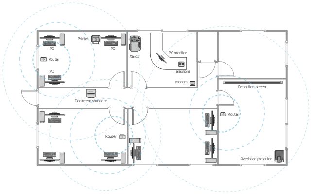
This office floor plan sample depicts the equipment layout of wireless computer network.
"A wireless local area network (WLAN) links two or more devices using some wireless distribution method (typically spread-spectrum or OFDM radio), and usually providing a connection through an access point to the wider Internet. This gives users the ability to move around within a local coverage area and still be connected to the network. Most modern WLANs are based on IEEE 802.11 standards, marketed under the Wi-Fi brand name." [Wireless LAN. Wikipedia]
The equipment layout example "Office wireless network plan" was created using the ConceptDraw PRO diagramming and vector drawing software extended with the Office Layout Plans solution from the Building Plans area of ConceptDraw Solution Park.
Equipment layout
Design Element: Rack Diagram for Network Diagrams
.png "Network Diagramming Tools, Design Elements - Rack Diagram (Win Mac)")
Rack Diagrams

- Network Layout Floor Plans | Design elements - Network layout ...
- Two Requirements And Equipment And Layouts Of Modern Drawing
- Network equipment and cabling layout - Template
- Network equipment and cabling layout - Template
- Network Layout Floor Plans | Ethernet cable layout | Home ...
- Network Layout Floor Plans | Local area network (LAN). Computer ...
- Class Room Furniture And Equipment Layout
- Computer Network Diagrams | How to Draw a Computer Network ...
- Requirements And Equipments For Layouts Of Modern Drawing
- Network equipment and cabling layout - Template | Network Layout ...
- Tree Network Topology Diagram | How to Draw a Computer Network ...
- Network Layout Floor Plans | Network Layout | Network equipment ...
- Network equipment and cabling layout - Template | Communication ...
- Network equipment and cabling layout - Template | Network layout ...
- Sample Computer Shop Layout Using Cisco
- Computer Lab Design Layout
- Design elements - Network layout floorplan | Network equipment ...
- Network Gateway Router | Network equipment and cabling layout ...
- Plant Layout Plans | Rack Diagrams | Machines and equipment ...
- Switch Rack Layout