Network Diagram Examples


"Physical topology refers to the placement of the network's various components, including device location and cable installation...
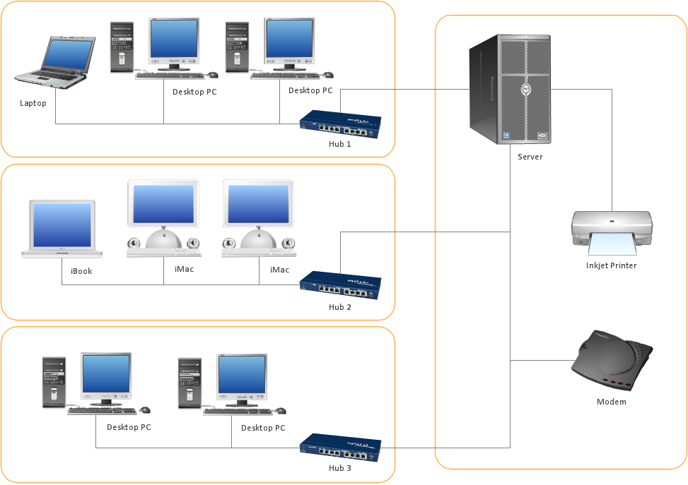
The shape of the cabling layout used to link devices is called the physical topology of the network. This refers to the layout of cabling, the locations of nodes, and the interconnections between the nodes and the cabling. The physical topology of a network is determined by the capabilities of the network access devices and media, the level of control or fault tolerance desired, and the cost associated with cabling or telecommunications circuits." [Network topology. Wikipedia]
This physical LAN diagram example was created using the ConceptDraw PRO diagramming and vector drawing software extended with the Computer and Networks solution from the Computer and Networks area of ConceptDraw Solution Park.
LAN physical topology

Used Solutions
Network Diagram Software Logical Network Diagram

Basic Network Diagram

 Cisco Network Diagrams
Cisco Network Diagrams solution extends ConceptDraw DIAGRAM with the best characteristics of network diagramming software. Included samples, templates and libraries of built-in standardized vector Cisco network icons and Cisco symbols of computers, network devices, network appliances and other Cisco network equipment will help network engineers, network designers, network and system administrators, as well as other IT professionals and corporate IT departments to diagram efficiently the network infrastructure, to visualize computer networks topologies, to design Cisco computer networks, and to create professional-looking Cisco Computer network diagrams, Cisco network designs and schematics, Network maps, and Network topology diagrams in minutes.
"Logical topology, or signal topology, is the arrangement of devices on a computer network and how they communicate with one another. How devices are connected to the network through the actual cables that transmit data, or the physical structure of the network, is called the physical topology. Physical topology defines how the systems are physically connected. It represents the physical layout of the devices on the network. The logical topology defines how the systems communicate across the physical topologies.
Logical topologies are bound to network protocols and describe how data is moved across the network. ...
EXAMPLE : twisted pair Ethernet is a logical bus topology in a physical star topology layout. while IBM's token ring is a logical ring topology, it is physically set up in star topology." [Logical topology. Wikipedia]
This Cisco logical computer network diagram example was created using the ConceptDraw PRO diagramming and vector drawing software extended with the Cisco Network Diagrams solution from the Computer and Networks area of ConceptDraw Solution Park.
Logical network topology diagram

ConceptDraw Arrows10 Technology
- Local Area Network Diagram
- Network Diagram Examples | Physical LAN and WAN diagram ...
- Network Diagram Examples | Basic Network Diagram | Network ...
- Local network physical topology floor plan | ConceptDraw PRO ...
- Physical LAN and WAN diagram template
- Home Area Network Example
- Diagram Physical Topologies | Hotel Network Topology Diagram ...
- Physical LAN and WAN diagram template | Network Diagram ...
- Diagram of a Wireless Network | Wireless Network WLAN ...
- Physical LAN and WAN diagram template | Computer network ...
- Network Diagram Software LAN Diagrams | Basic Network Diagram ...
- Network Diagram Software. LAN Diagrams | Network Diagram ...
- Complete Network Topology | Fully Connected Network Topology ...
- Tree Network Topology Diagram | Network Topologies | Star ...
- Network Diagram Software Home Area Network | Wan And Lan ...
- Network Diagram Examples | Physical LAN and WAN diagram ...
- Network Diagram Software LAN Diagrams | Network Diagram ...
- Physical LAN diagram | Network Diagram Software LAN Diagrams ...
- Logical network topology diagram | Cisco logical network diagram ...
- Network Diagram Software LAN Diagrams | How to Draw a ...