The vector stencils library "HR flowchart" contains 62 flowchart symbols.
Use it to draw your HR flowcharts, workflow diagrams and process charts with the ConceptDraw PRO diagramming and vector drawing software.
The flow chart symbols library "HR flowchart" is included in the HR Flowcharts solution from the Management area of ConceptDraw Solution Park.
Use it to draw your HR flowcharts, workflow diagrams and process charts with the ConceptDraw PRO diagramming and vector drawing software.
The flow chart symbols library "HR flowchart" is included in the HR Flowcharts solution from the Management area of ConceptDraw Solution Park.
Annotation
Card

Check / audit (diamond)
-hr-flowchart---vector-stencils-library.png--diagram-flowchart-example.png)
Check / audit (square)
-hr-flowchart---vector-stencils-library.png--diagram-flowchart-example.png)
Collate

Comment / note symbol (brace)
-hr-flowchart---vector-stencils-library.png--diagram-flowchart-example.png)
Communication link
Compare (diamond)
-hr-flowchart---vector-stencils-library.png--diagram-flowchart-example.png)
Compare (square)
-hr-flowchart---vector-stencils-library.png--diagram-flowchart-example.png)
Completed form

Concurrency symbol (fork / join)
-hr-flowchart---vector-stencils-library.png--diagram-flowchart-example.png)
Conditional selector
Control transfer
Data input / output

Database
Decision

Decision indicator - No
Decision indicator - Yes

Delay

Direct access storage

Disk storage
Display

Divided process (table view)
-hr-flowchart---vector-stencils-library.png--diagram-flowchart-example.png)
Document

Entity (rounded)
-hr-flowchart---vector-stencils-library.png--diagram-flowchart-example.png)
Event

Extract

Flow line
Internal storage

Junction symbol

Lined document

Lined / shaded process

Loop limit

Manual file

Manual input

Manual operation

Merge

Multi document

Multi process

Off-page reference - arrow
Off-page reference - incoming

Off-page reference - outgoing

On-page reference/ Inspection point

Or
Page

Paper tape

Predefined process

Prepare conditional

Process step

Reference point

Sequential access storage

Sort

Start (circle)
-hr-flowchart---vector-stencils-library.png--diagram-flowchart-example.png)
Start (ellipse)
-hr-flowchart---vector-stencils-library.png--diagram-flowchart-example.png)
Stickman pictogram

Stored data

Summary

Tagged document

Tagged process

Terminal point
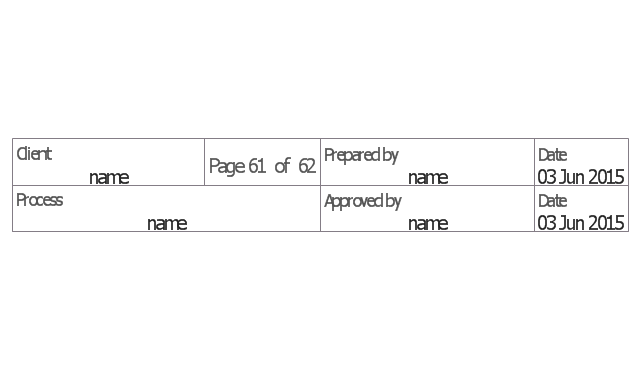
Title block
Torso pictogram

HelpDesk
Event-driven Process Chain (EPC) Diagram Software

The vector stencils library "Sales flowchart" contains 62 sales process flow chart symbols.
Use these flow chart icon set to draw your sales flowcharts, workflow diagrams and process charts with the ConceptDraw PRO diagramming and vector drawing software.
The sales process flowchart symbols library "Sales flowchart" is included in the Sales Flowcharts solution from the Marketing area of ConceptDraw Solution Park.
Annotation
Card

Check / audit (diamond)
-sales-flowchart---vector-stencils-library.png--diagram-flowchart-example.png)
Check / audit (square)
-sales-flowchart---vector-stencils-library.png--diagram-flowchart-example.png)
Collate

Comment / note symbol (brace)
-sales-flowchart---vector-stencils-library.png--diagram-flowchart-example.png)
Communication link
Compare (diamond)
-sales-flowchart---vector-stencils-library.png--diagram-flowchart-example.png)
Compare (square)
-sales-flowchart---vector-stencils-library.png--diagram-flowchart-example.png)
Completed form

Concurrency symbol (fork / join)
-sales-flowchart---vector-stencils-library.png--diagram-flowchart-example.png)
Conditional selector
Control transfer
Database
Data input / output

Decision

Decision indicator - No
Decision indicator - Yes

Delay

Direct access storage

Disk storage
Display

Divided process (table view)
-sales-flowchart---vector-stencils-library.png--diagram-flowchart-example.png)
Document

Entity (rounded)
-sales-flowchart---vector-stencils-library.png--diagram-flowchart-example.png)
Event

Extract

Flow line
Internal storage

Junction symbol

Lined document

Lined / shaded process

Loop limit

Manual file

Manual input

Manual operation

Merge

Multi document

Multi process

Off-page reference - arrow
Off-page reference - incoming

Off-page reference - outgoing

On-page reference/ Inspection point

Or
Page

Paper tape

Predefined process

Prepare conditional

Process step

Reference point

Sequential access storage

Sort

Start (circle)
-sales-flowchart---vector-stencils-library.png--diagram-flowchart-example.png)
Start (ellipse)
-sales-flowchart---vector-stencils-library.png--diagram-flowchart-example.png)
Stickman pictogram

Stored data

Summary

Tagged document

Tagged process

Terminal point

Title block

Torso pictogram

The vector stencils library "HR flowchart" contains 62 flowchart symbols.
Use it to draw your HR flowcharts, workflow diagrams and process charts with the ConceptDraw PRO diagramming and vector drawing software.
The flow chart symbols library "HR flowchart" is included in the HR Flowcharts solution from the Management area of ConceptDraw Solution Park.
Use it to draw your HR flowcharts, workflow diagrams and process charts with the ConceptDraw PRO diagramming and vector drawing software.
The flow chart symbols library "HR flowchart" is included in the HR Flowcharts solution from the Management area of ConceptDraw Solution Park.
Annotation
Card
Check / audit (diamond)
Check / audit (square)
Collate
Comment / note symbol (brace)
Communication link
Compare (diamond)
Compare (square)
Completed form
Concurrency symbol (fork / join)
Conditional selector
Control transfer
Data input / output
Database
Decision
Decision indicator - No
Decision indicator - Yes
Delay
Direct access storage
Disk storage
Display
Divided process (table view)
Document
Entity (rounded)
Event
Extract
Flow line
Internal storage
Junction symbol
Lined document
Lined / shaded process
Loop limit
Manual file
Manual input
Manual operation
Merge
Multi document
Multi process
Off-page reference - arrow
Off-page reference - incoming
Off-page reference - outgoing
On-page reference/ Inspection point
Or
Page
Paper tape
Predefined process
Prepare conditional
Process step
Reference point
Sequential access storage
Sort
Start (circle)
Start (ellipse)
Stickman pictogram
Stored data
Summary
Tagged document
Tagged process
Terminal point
Title block
Torso pictogram
The vector stencils library "HVAC controls" contains 23 symbols of HVAC controls (sensors, actuators, timers, controllers, I/ O points).
"HVAC (... Heating, Ventilation and Air Conditioning) is a control system that applies regulation to a heating and/ or air conditioning system. ...
Central controllers and most terminal unit controllers are programmable, meaning the direct digital control program code may be customized for the intended use. The program features include time schedules, setpoints, controllers, logic, timers, trend logs, and alarms. The unit controllers typically have analog and digital inputs that allow measurement of the variable (temperature, humidity, or pressure) and analog and digital outputs for control of the transport medium (hot/ cold water and/ or steam). Digital inputs are typically (dry) contacts from a control device, and analog inputs are typically a voltage or current measurement from a variable (temperature, humidity, velocity, or pressure) sensing device. Digital outputs are typically relay contacts used to start and stop equipment, and analog outputs are typically voltage or current signals to control the movement of the medium (air/ water/ steam) control devices such as valves, dampers, and motors." [HVAC control system. Wikipedia]
Use the design elements library "HVAC controls" for drawing the HVAC system diagrams, controls drawings, and automated building control and environmental control system layuout floor plans using the ConceptDraw PRO diagramming and vector drawing software.
The shapes library "HVAC controls" is included in the HVAC Plans solution from the Building Plans area of ConceptDraw Solution Park.
HVAC control symbols

The vector stencils library "Delay elements" contains 12 symbols of delay elements for drawing electrical schematics and electronic circuit diagrams.
"An analog delay line is a network of electrical components connected in series, where each individual element creates a time difference or phase change between its input signal and its output signal. It operates on analog signals whose amplitude varies continuously. An example is a bucket-brigade device. Other types of delay line include acoustic, magnetostrictive, and surface acoustic wave devices. A series of RC networks can be cascaded to form a delay. A long transmission line can also provide a delay element. The delay time of an analog delay line may be only a few nanoseconds or several milliseconds, limited by the practical size of the physical medium used to delay the signal and the propagation speed of impulses in the medium." [Analog delay line. Wikipedia]
The symbols example "Design elements - Delay elements" was drawn using the ConceptDraw PRO diagramming and vector drawing software extended with the Electrical Engineering solution from the Engineering area of ConceptDraw Solution Park.
Delay element symbols

The vector stencils library "Transformers and windings" contains 29 element symbols of transformers, windings, couplers, metering devices, transductors, magnetic cores, chokes, and a variometer.
Use it to design the electromechanical device schematics and electronic circuit diagrams.
"A transformer is an electrical device that transfers energy between two circuits through electromagnetic induction. Transformers may be used in step-up or step-down voltage conversion, which 'transforms' an AC voltage from one voltage level on the input of the device to another level at the output terminals. This special function of transformers can provide control of specified requirements of current level as an alternating current source, or it may be used for impedance matching between mismatched electrical circuits to effect maximum power transfer between the circuits.
A transformer most commonly consists of two windings of wire that are wound around a common core to induce tight electromagnetic coupling between the windings. The core material is often a laminated iron core. The coil that receives the electrical input energy is referred to as the primary winding, while the output coil is called the secondary winding.
An alternating electric current flowing through the primary winding (coil) of a transformer generates an electromagnetic field in its surroundings and a varying magnetic flux in the core of the transformer. By electromagnetic induction this magnetic flux generates a varying electromotive force in the secondary winding, resulting in a voltage across the output terminals. If a load impedance is connected across the secondary winding, a current flows through the secondary winding drawing power from the primary winding and its power source." [Transformer. Wikipedia]
"An electromagnetic coil (or simply a "coil") is formed when a conductor is wound around a core or form to create an inductor or electromagnet. When electricity is passed through a coil, it generates a magnetic field. One loop of wire is usually referred to as a turn or a winding, and a coil consists of one or more turns. For use in an electronic circuit, electrical connection terminals called taps are often connected to a coil. Coils are often coated with varnish or wrapped with insulating tape to provide additional insulation and secure them in place. A completed coil assembly with one or more set of coils and taps is often called the windings.
Windings are used in transformers, electric motors, inductors, solenoids, loudspeakers, and many other applications." [Electromagnetic coil. Wikipedia]
The shapes example "Design elements - Transformers and windings" was drawn using the ConceptDraw PRO diagramming and vector drawing software extended with the Electrical Engineering solution from the Engineering area of ConceptDraw Solution Park.
Transformer and winding symbols

The vector stencils library "IDEF0 diagrams" contains 18 symbols for drawing IDEF0 function modeling diagrams using the ConceptDraw PRO diagramming and vector drawing software.
"The IDEF0 model ... is based on a simple syntax. Each activity is described by a verb-based label placed in a box. Inputs are shown as arrows entering the left side of the activity box while output are shown as exiting arrows on the right side of the box. Controls are displayed as arrows entering the top of the box and mechanisms are displayed as arrows entering from the bottom of the box. Inputs, Controls, Outputs, and Mechanisms are all referred to as concepts.
- Arrow : A directed line, composed of one or more arrow segments, that models an open channel or conduit conveying data or objects from source (no arrowhead) to use (with arrowhead). There are 4 arrow classes: Input Arrow, Output Arrow, Control Arrow, and Mechanism Arrow (includes Call Arrow). See Arrow Segment, Boundary Arrow, Internal Arrow.
- Box : A rectangle, containing a name and number, used to represent a function.
- Context : The immediate environment in which a function (or set of functions on a diagram) operates.
- Decomposition : The partitioning of a modeled function into its component functions.
- Fork : The junction at which an IDEF0 arrow segment (going from source to use) divides into two or more arrow segments. May denote unbundling of meaning.
- Function : An activity, process, or transformation (modeled by an IDEF0 box) identified by a verb or verb phrase that describes what must be accomplished.
- Join : The junction at which an IDEF0 arrow segment (going from source to use) merges with one or more other arrow segments to form a single arrow segment. May denote bundling of arrow segment meanings.
- Node : A box from which child boxes originate; a parent box. See Node Index, Node Tree, Node Number, Node Reference, Diagram Node Number." [IDEF0. Wikipedia]
The example "Design elements - IDEF0 diagram" is included in the IDEF0 Diagrams solution from the Software Development area of ConceptDraw Solution Park.
IDEF0 symbols

- Flowchart Input Symbol
- Basic Flowchart Symbols and Meaning | Flowchart | Product ...
- Technical Flow Chart | Basic Flowchart Symbols and Meaning ...
- Basic Flowchart Symbols and Meaning | Account Flowchart ...
- Basic Flowchart Symbols and Meaning | HR flowchart - Vector ...
- Input Symbol For Flowchart
- Flowchart design. Flowchart symbols , shapes, stencils and icons ...
- Data Flow Diagram Symbols . DFD Library | Basic Flowchart ...
- Input Output Sales Flowchart
- Basic Flowchart Symbols and Meaning | Flowchart design ...
- Basic Flowchart Symbols and Meaning | How to Draw a Flowchart ...
- Single Line Electrical Lamp Symbol
- Data Flow Diagram | Process Flowchart | Types of Flowchart ...
- Basic Flowchart Symbols and Meaning | Cross-functional flowcharts ...
- Basic Flowchart Symbols and Meaning | Design elements - IDEF0 ...
- Basic Flowchart Symbols and Meaning | Accounting flowcharts ...
- Basic Flowchart Symbols and Meaning | Database Flowchart ...
- Flowchart Contains 26 Symbols For Drawing Flowcharts
- Data Flow Diagram | Data Flow Diagram Symbols . DFD Library ...
- Block Diagram | Basic Flowchart Symbols and Meaning ...