 Flowcharts
The Flowcharts solution for ConceptDraw DIAGRAM is a comprehensive set of examples and samples in several varied color themes for professionals that need to represent graphically a process. Solution value is added by the basic flow chart template and shapes' libraries of flowchart notation. ConceptDraw DIAGRAM flow chart creator lets one depict the processes of any complexity and length, as well as design the Flowchart either vertically or horizontally.
ERD Symbols and Meanings


Network Security Tips

 Chemical and Process Engineering
This chemical engineering solution extends ConceptDraw DIAGRAM.9.5 (or later) with process flow diagram symbols, samples, process diagrams templates and libraries of design elements for creating process and instrumentation diagrams, block flow diagrams (BFD
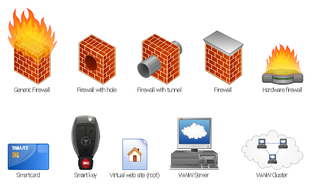
The vector stencils library "Internet symbols" contains 11 icons of equipment symbols.
Use these Web shapes for drawing computer network diagrams using the ConceptDraw PRO diagramming and vector drawing software.
The clipart example "Design elements - Internet symbols" is included in the Computer and Networks solution from the Computer and Networks area of ConceptDraw Solution Park.
Use these Web shapes for drawing computer network diagrams using the ConceptDraw PRO diagramming and vector drawing software.
The clipart example "Design elements - Internet symbols" is included in the Computer and Networks solution from the Computer and Networks area of ConceptDraw Solution Park.
Internet symbols
This pinout diagram example showing a VGA connector (as viewed from the socket) was redesigned from the Wikimedia Commons file: DE15 Connector Pinout.svg. [commons.wikimedia.org/ wiki/ File:DE15_ Connector_ Pinout.svg]
"A Video Graphics Array (VGA) connector is a three-row 15-pin DE-15 connector. The 15-pin VGA connector is found on many video cards, computer monitors, and high definition television sets. On laptop computers or other small devices, a mini-VGA port is sometimes used in place of the full-sized VGA connector.
DE-15 is also conventionally called RGB connector, D-sub 15, mini sub D15, mini D15, DB-15, HDB-15, HD-15 or HD15 (High Density, to distinguish it from the older and less flexible DE-9 connector used on some older VGA cards, which has the same shell size but only two rows of pins).
VGA connectors and cables carry analog component RGBHV (red, green, blue, horizontal sync, vertical sync) video signals, and VESA Display Data Channel (VESA DDC) data. In the original version of DE-15 pinout, one pin was keyed by plugging the female connector hole; this prevented non-VGA 15 pin cables from being plugged into a VGA socket. Four pins carried Monitor ID bits which were rarely used; VESA DDC redefined some of these pins and replaced the key pin with +5 V DC power supply.
The VGA interface is not engineered to be hotpluggable (so that the user can connect or disconnect the output device while the host is running), although in practice this can be done and usually does not cause damage to the hardware or other problems. However, nothing in the design ensures that the ground pins make a connection first and break last, so hotplugging may introduce surges in signal lines which may or may not be adequately protected against. Also, depending on the hardware and software, detecting a monitor being connected might not work properly in all cases." [VGA connector. Wikipedia]
The pinout diagram example "VGA connector pinout" was created using the ConceptDraw PRO diagramming and vector drawing software extended with the Audio and Video Connectors solution from the Engineering area of ConceptDraw Solution Park.
VGA connector pinout

Bank Detailed Answers

 Education Mind Maps
This solution extends ConceptDraw MINDMAP software with scientific and educational mind maps for educational documents, presentations, and websites.
- Continent Maps | Cool Id Card Background Design Red
- Internet symbols - Vector stencils library | Internet symbols - Vector ...
- Internet symbols - Vector stencils library | Secure Id Card
- Internet symbols - Vector stencils library | Design elements - Internet ...
- Design elements - Internet symbols | Internet symbols - Vector ...
- Cisco Security. Cisco icons, shapes, stencils and symbols | Internet ...
- Home Electrical Plan | Astronomy Symbols | Flowchart design ...
- Use Case Diagram For Online Id Card Processing System
- Internet Vsat Id Card
- How to Support Your Mind Map with Visual Elements | Design ...
- Internet symbols - Vector stencils library | Firewall between LAN and ...
- Design elements - Network layout floorplan | Network Diagram ...
- Cisco Network Design . Cisco icons, shapes, stencils, symbols and ...
- Internet symbols - Vector stencils library | Internet symbols - Vector ...
- UML Activity Diagram | Diagramming Software for Design UML ...
- Example of DFD for Online Store (Data Flow Diagram) DFD ...
- Cisco Network Topology. Cisco icons, shapes, stencils and symbols ...
- UML Flowchart Symbols | UML Component Diagram | Swim Lane ...
- Internet symbols - Vector stencils library | Data Flow Diagram ...
- Internet symbols - Vector stencils library | Access and security ...