The vector stencil library "HVAC ductwork" contains 63 duct and vent symbols.
Use it for drawing HVAC system diagrams, heating, ventilation, air conditioning, refrigeration, automated building control, and environmental control design floor
plans and equipment layouts.
"Ducts are used in heating, ventilation, and air conditioning (HVAC) to deliver and remove air. These needed airflows include, for example, supply air, return air, and exhaust air. Ducts also deliver, most commonly as part of the supply air, ventilation air. As such, air ducts are one method of ensuring acceptable indoor air quality as well as thermal comfort.
A duct system is often called ductwork. Planning ('laying out'), sizing, optimizing, detailing, and finding the pressure losses through a duct system is called duct design." [Duct (HVAC). Wikipedia]
The vector stencils example "Design elements - HVAC ductwork" is included in HVAC Plans solution from the Building Plans area of ConceptDraw Solution Park.
HVAC ductwork symbols

The vector stencils library "HVAC ductwork" contains 55 duct and vent symbols of HVAC mechanical components. Use it for drawing HVAC ductwork system diagrams, heating, ventilation, air conditioning, refrigeration, automated building control, and environmental control design in the ConceptDraw PRO diagramming and vector drawing software extended with the HVAC Plans solution from the Building Plans area of ConceptDraw Solution Park.
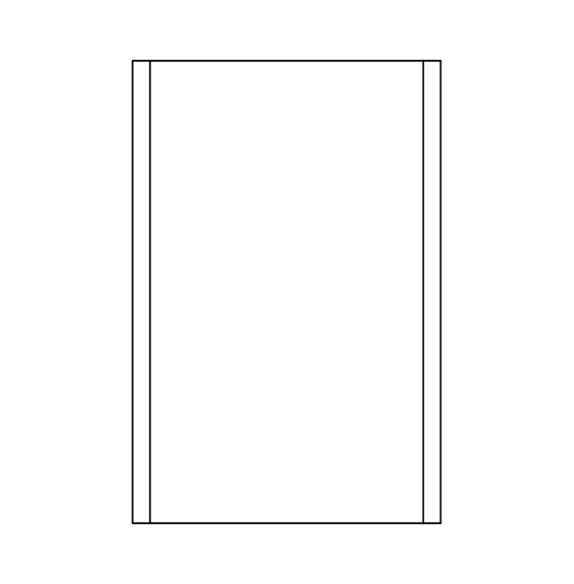
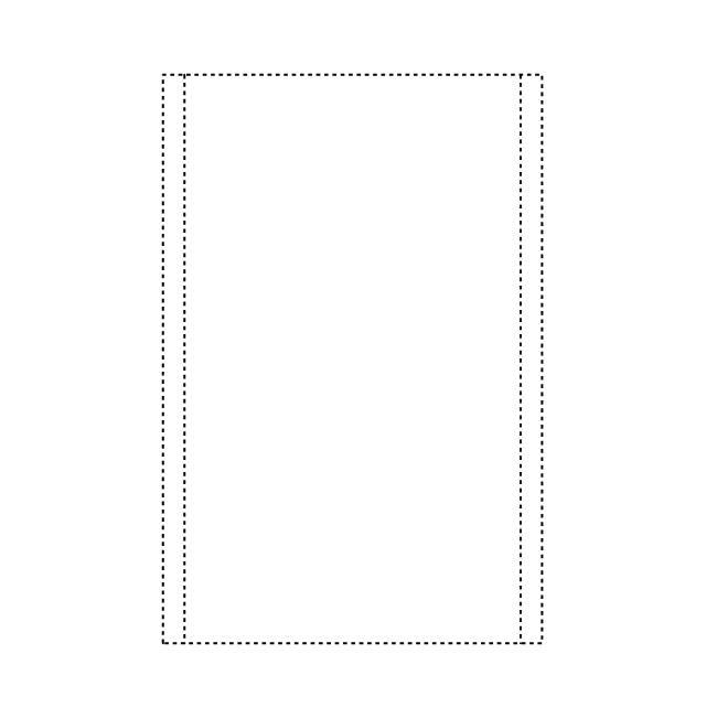
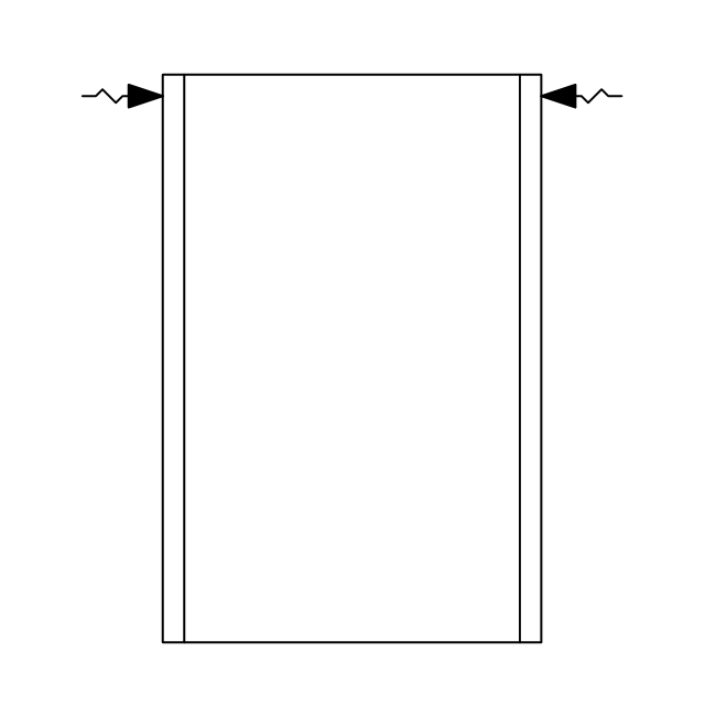
Rect. duct, closed ends

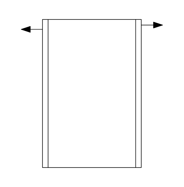
Rect. duct, open 1 end

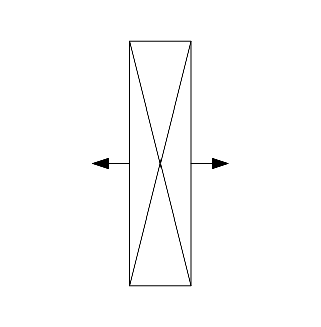
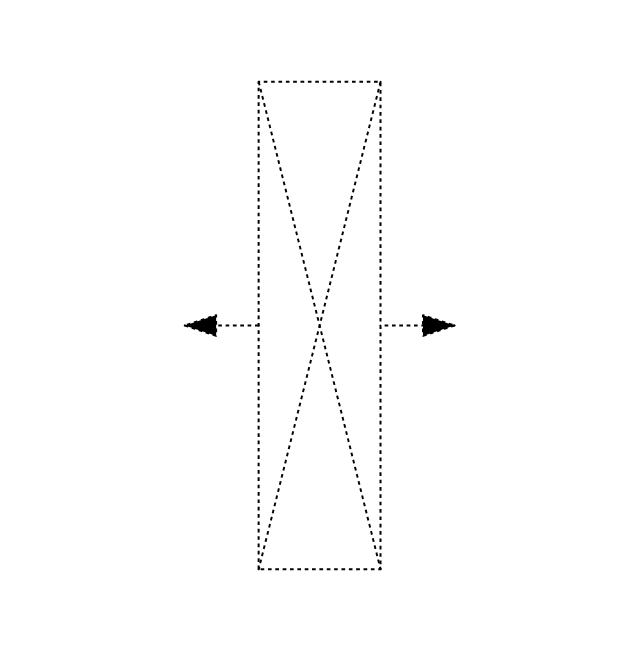
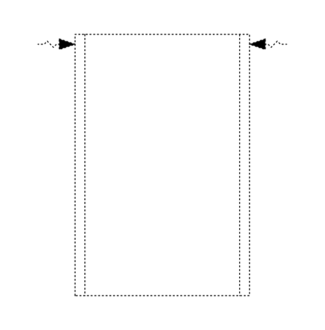
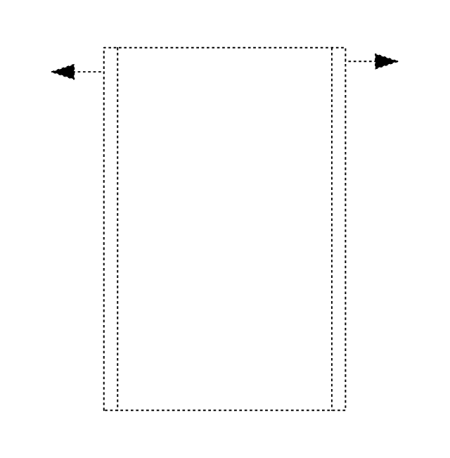
Rect. duct, open both ends

Circ. duct, closed ends

Circ. duct, open 1 end

Circ. duct, open both ends

Branch duct, rectangular

Branch duct, circular

Variable bend

Miter bend

Y junction

3 way junction

Junction 1

Beveled junction, rect. duct, rect. branch

Beveled junction, rect. duct, circ. branch

Beveled junction, circ. duct, rect. branch

Beveled junction, circ. duct, circ. branch

Transition, rect. to rect.

Transition, rect. to circ.

Transition, circ. to rect.

Transition, circ. to circ.

Offset transition, rect. to rect.

Offset transition, rect. to circ.

Offset transition, circ. to rect.

Offset transition, circ. to circ.

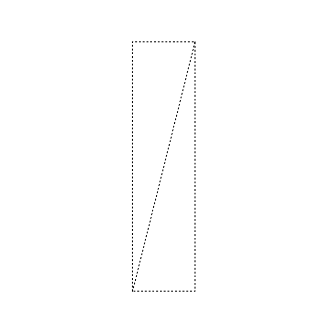
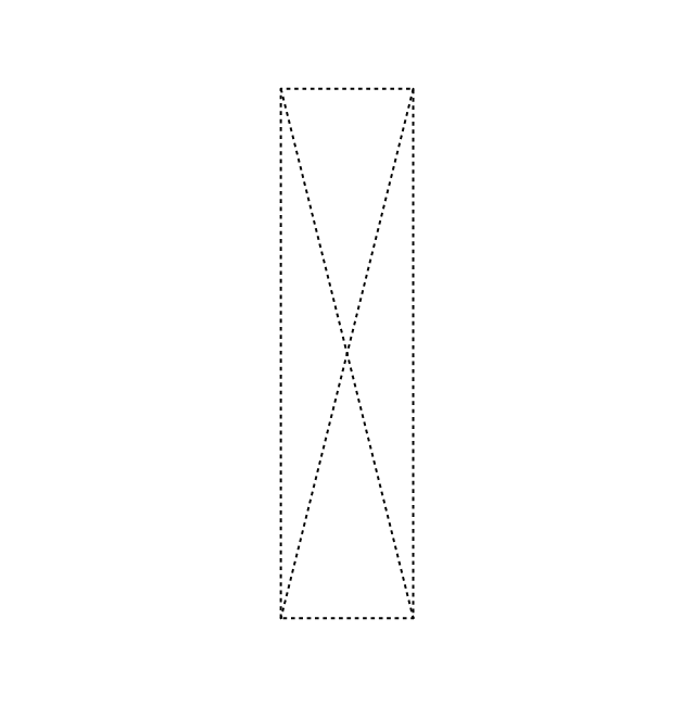
Flexible connection, rect. duct

Flexible connection, circ. duct

Flexible connection 2, rect. duct

Flexible connection 2, circ. duct

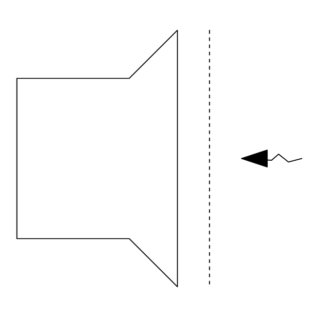
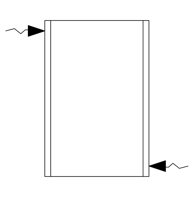
Supply, rect. duct toward

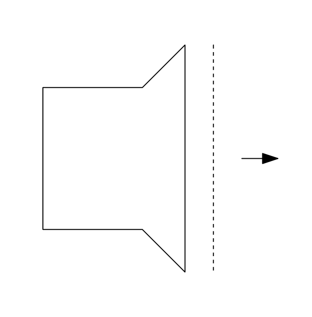
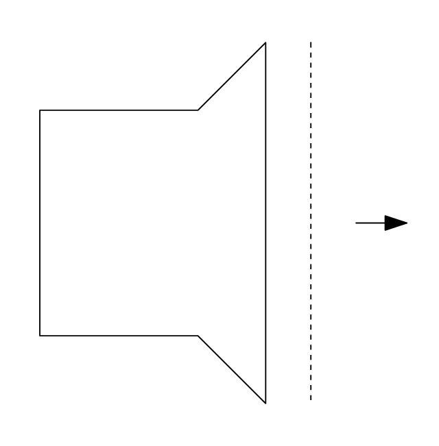
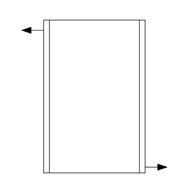
Supply, rect. duct away

Supply, rect. duct, elbow away

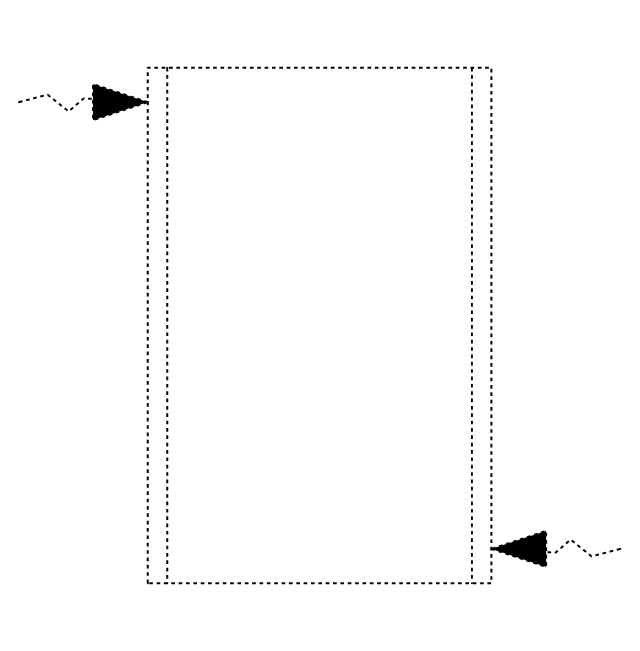
Supply, circ. duct toward

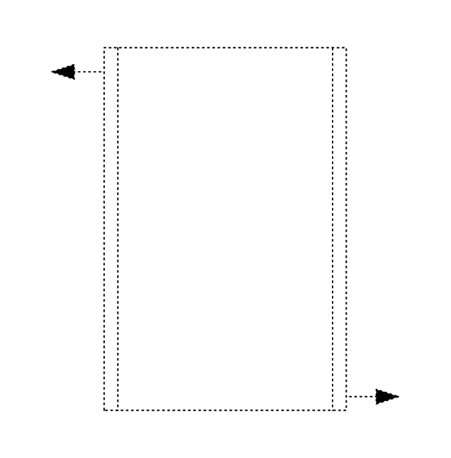
Supply, circ. duct away

Supply, circ. duct, elbow away

Return, rect. duct toward

Return, rect. duct away

Return, rect. duct, elbow away

Return, circ. duct toward

Return, circ. duct away

Return, circ. duct, elbow away

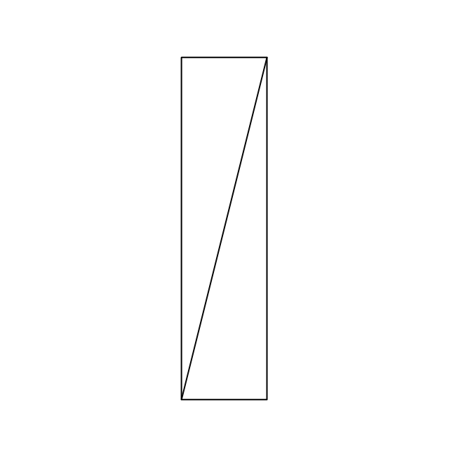
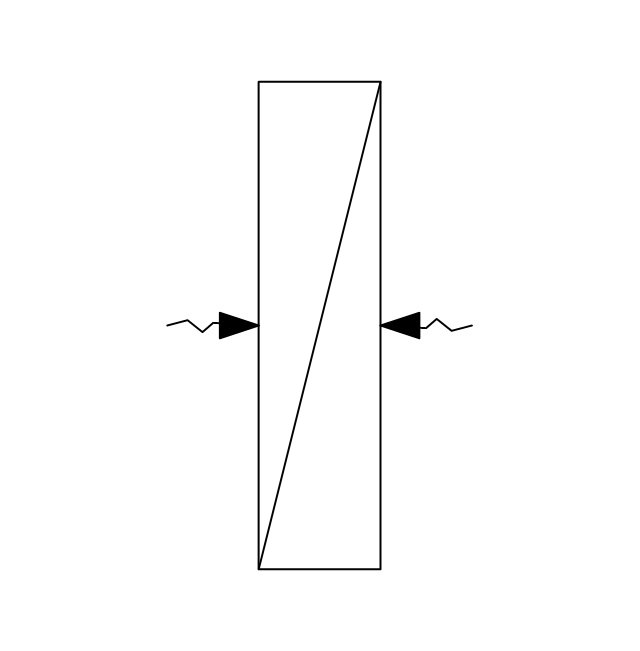
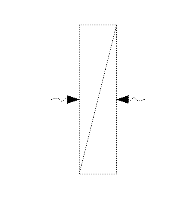
Sliding damper, rect. duct

Sliding damper, circ. duct

Damper, ACD

Damper, BD

Damper, FD/AD

Damper, MD

Damper, SD/AD

Vert. duct, rect. duct toward

Vert. duct, rect. duct away

Vert. duct, rect. duct, elbow away

Vert. duct, circ. duct toward

Vert. duct, circ. duct away

Vert. duct, circ. duct, elbow away

VAV box

This HVAC floor plan sample illustrates the temperature sensors of air handler digital thermostat control.
"A thermostat is a component of a control system which senses the temperature of a system so that the system's temperature is maintained near a desired setpoint. The thermostat does this by switching heating or cooling devices on or off, or regulating the flow of a heat transfer fluid as needed, to maintain the correct temperature. The name is derived from the Greek words thermos "hot" and statos "a standing".
A thermostat may be a control unit for a heating or cooling system or a component part of a heater or air conditioner. Thermostats can be constructed in many ways and may use a variety of sensors to measure the temperature. The output of the sensor then controls the heating or cooling apparatus. A thermostat may switch on and off at temperatures either side of the setpoint the extent of the difference is known as hysteresis and prevents too frequent switching of the controlled equipment." [Thermostat. Wikipedia]
The HVAC plan example "Digital unit ventilator control" was created using the ConceptDraw DIAGRAM diagramming and vector drawing software extended with the HVAC Plans solution from the Building Plans area of ConceptDraw Solution Park.
HVAC floor plan

 HVAC Plans
Use HVAC Plans solution to create professional, clear and vivid HVAC-systems design plans, which represent effectively your HVAC marketing plan ideas, develop plans for modern ventilation units, central air heaters, to display the refrigeration systems for automated buildings control, environmental control, and energy systems.
Interior Design. Registers, Drills and Diffusers — Design Elements

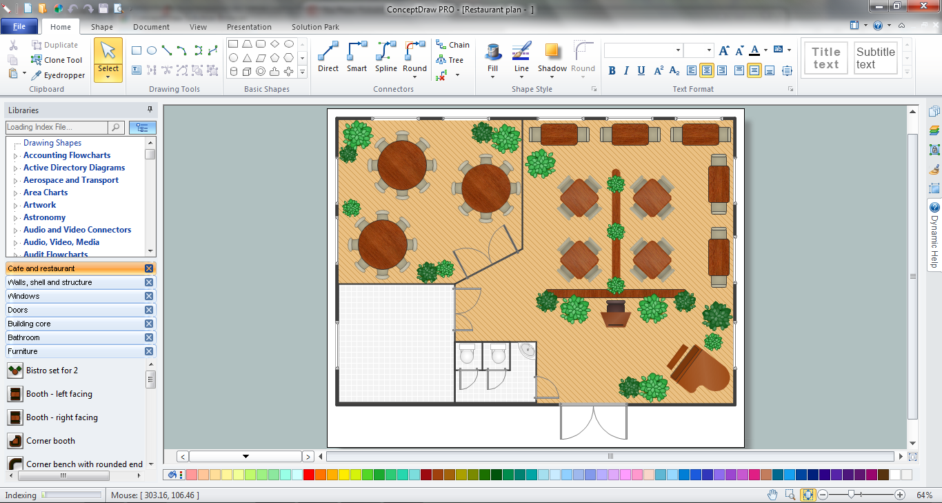
 Cafe and Restaurant Floor Plans
Restaurants and cafes are popular places for recreation, relaxation, and are the scene for many impressions and memories, so their construction and design requires special attention. Restaurants must to be projected and constructed to be comfortable and e
The vector stencils library Registers, drills and diffusers contains 47 symbols of rectangular, circular, linear and troffer air handling inlet/ outlet components.
Use the design elements library Registers, drills and diffusers to draw reflected ceiling plans (RCP) and HVAC layout floor plans using the ConceptDraw PRO diagramming and vector drawing software.
"A ceiling is an overhead interior surface that covers the upper limit of a room. It is not generally considered a structural element, but a finished surface concealing the underside of the floor or roof structure above.
Ceilings are classified according to their appearance or construction. A cathedral ceiling is any tall ceiling area similar to those in a church. A dropped ceiling is one in which the finished surface is constructed anywhere from a few inches to several feet below the structure above it. This may be done for aesthetic purposes, such as achieving a desirable ceiling height; or practical purposes such as providing a space for HVAC or piping. An inverse of this would be a raised floor. A concave or barrel shaped ceiling is curved or rounded, usually for visual or acoustical value, while a coffered ceiling is divided into a grid of recessed square or octagonal panels, also called a "lacunar ceiling". A cove ceiling uses a curved plaster transition between wall and ceiling; it is named for cove molding, a molding with a concave curve." [Ceiling. Wikipedia]
"... reflected Ceiling Plans (RCP)s showing ceiling layouts appear after the floor plans." [Plan (drawing). Wikipedia]
The shapes library "Registers, drills and diffusers" is contained in the Reflected Ceiling Plans solution from the Building Plans area of ConceptDraw Solution Park.
Reflected ceiling plan symbols

 Venn Diagrams
Venn Diagrams are actively used to illustrate simple set relationships in set theory and probability theory, logic and statistics, mathematics and computer science, linguistics, sociology, and marketing. Venn Diagrams are also often used to visually summarize the status and future viability of a project.
 Circle-Spoke Diagrams
Examples of subject areas that are well suited to this approach are marketing, business, products promotion, process modeling, market, resource, time, and cost analysis. Circle-Spoke Diagrams are successfully used in presentations, conferences, management documents, magazines, reportages, reviews, reports, TV, and social media.
The vector stencils library "Registers, drills and diffusers" contains 47 shapes of rectangular, circular, linear and troffer air handling inlet/ outlet components, registers, drills and diffusers. Use it for drawing reflected ceiling plans and HVAC plans in the ConceptDraw PRO diagramming and vector drawing software extended with the Reflected Ceiling Plans solution from the Building Plans area of ConceptDraw Solution Park.
Rectangular inlet
Rectangular inlet, hidden
Rectangular inlet, flow arrow
Rectangular inlet, flow arrow, hidden
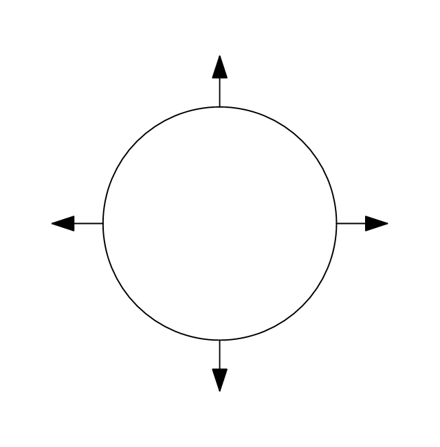
Circular inlet
Circular inlet, hidden
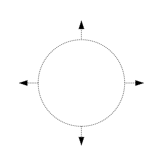
Circular inlet, flow arrow
Circular inlet, flow arrow, hidden
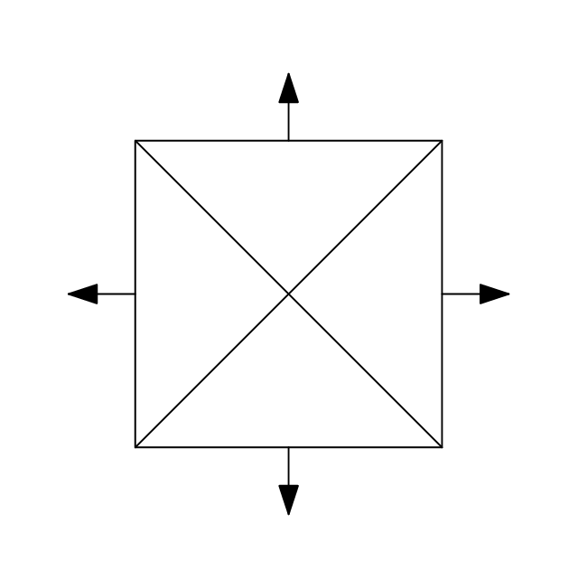
Rectangular outlet
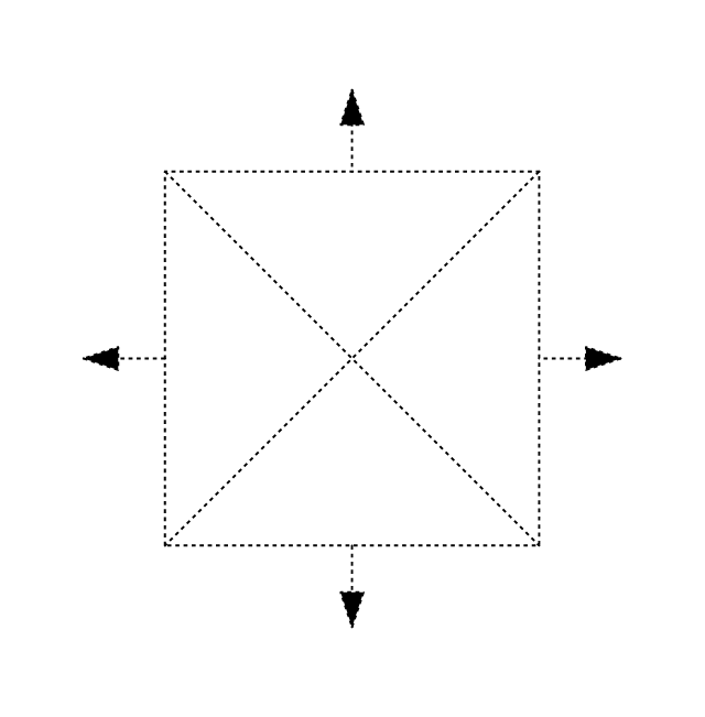
Rectangular outlet, hidden
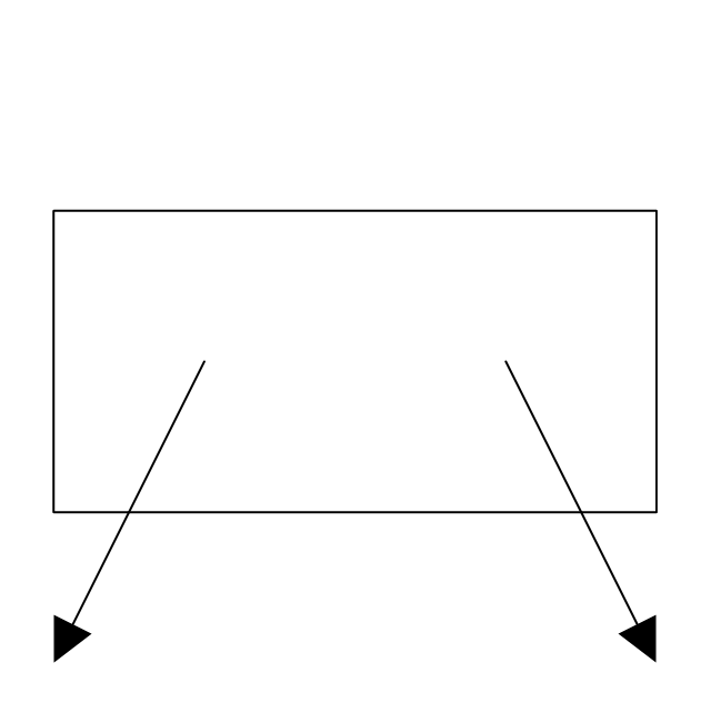
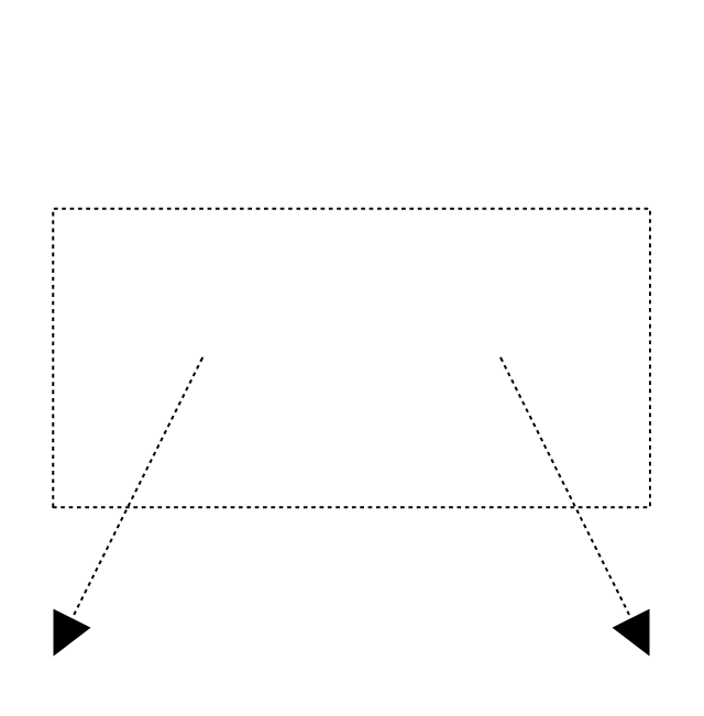
Rectangular outlet, flow arrows
Rectangular outlet, flow arrows, hidden
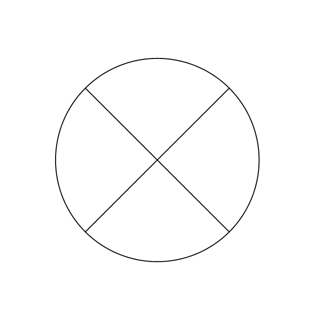
Circular outlet
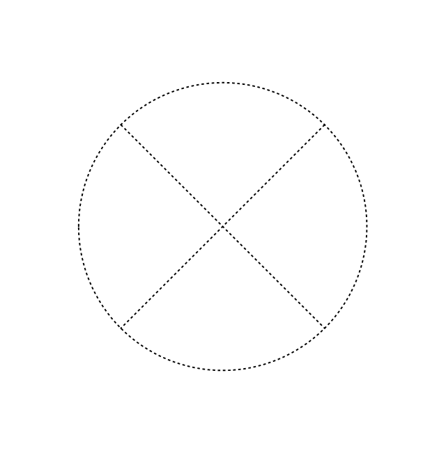
Circular outlet, hidden
Circular outlet, flow arrows
Circular outlet, flow arrows, hidden
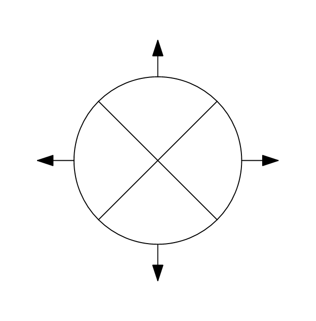
Grille diffuser, rectangular duct
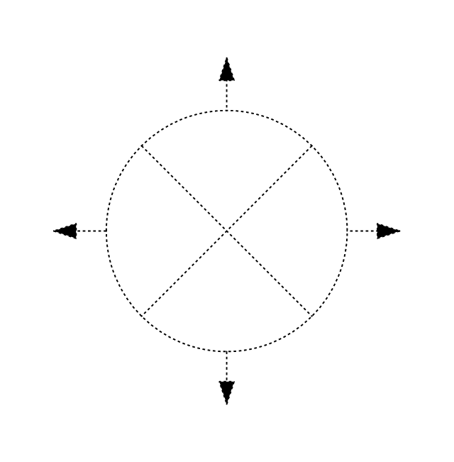
Grille diffuser, circular duct

Return grille diffuser, rectangular duct
Return grille diffuser, circular duct
Supply grille diffuser, rectangular duct
Supply grille diffuser, circular duct
Linear return diffuser
Linear return diffuser, hidden
Linear supply diffuser

Linear supply diffuser, hidden
Linear return diffuser, flow arrows
Linear return diffuser, flow arrows, hidden
Linear supply diffuser, flow arrows
Linear supply diffuser, flow arrows, hidden
Troffer inlet / outlet
Troffer inlet / outlet, hidden
Troffer inlet, return diffuser
Troffer inlet, return diffuser, hidden
Troffer inlet, supply diffuser
Troffer inlet, supply diffuser, hidden
Troffer outlet, return diffuser
Troffer outlet, return diffuser, hidden
Troffer outlet, supply diffuser
Troffer outlet, supply diffuser, hidden
Circular outlet
Circular outlet, hidden
Grille
Grille, hidden
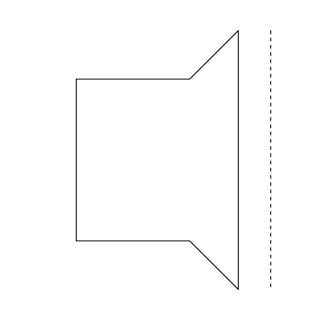
Grille (side)
-registers,-drills-and-diffusers---vector-stencils-library.png--diagram-flowchart-example.png)
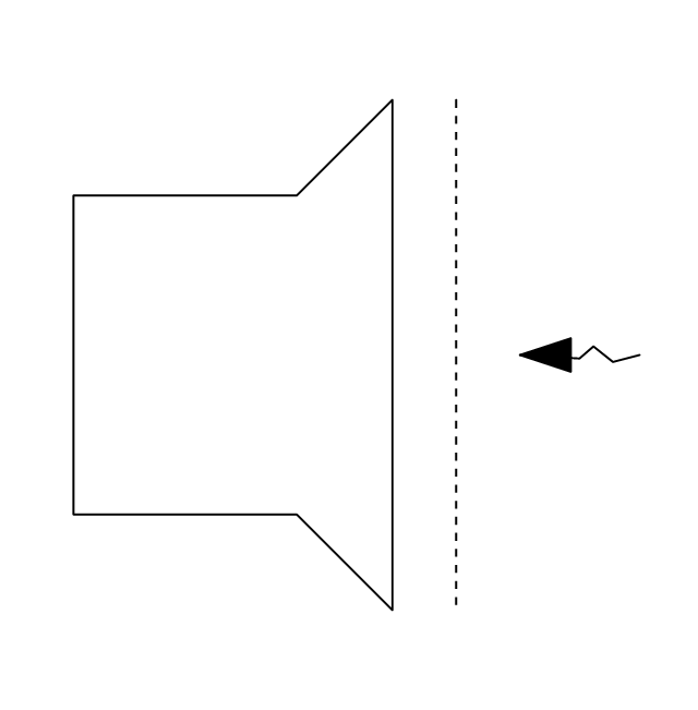
Grille (side), return diffuser
,-return-diffuser-registers,-drills-and-diffusers---vector-stencils-library.png--diagram-flowchart-example.png)
Grille (side), supply diffuser
,-supply-diffuser-registers,-drills-and-diffusers---vector-stencils-library.png--diagram-flowchart-example.png)
 Mechanical Engineering
This solution extends ConceptDraw DIAGRAM.9 mechanical drawing software (or later) with samples of mechanical drawing symbols, templates and libraries of design elements, for help when drafting mechanical engineering drawings, or parts, assembly, pneumatic,
 Event-driven Process Chain Diagrams
Event-Driven Process Chain Diagrams solution extends ConceptDraw DIAGRAM functionality with event driven process chain templates, samples of EPC engineering and modeling the business processes, and a vector shape library for drawing the EPC diagrams and EPC flowcharts of any complexity. It is one of EPC IT solutions that assist the marketing experts, business specialists, engineers, educators and researchers in resources planning and improving the business processes using the EPC flowchart or EPC diagram. Use the EPC solutions tools to construct the chain of events and functions, to illustrate the structure of a business process control flow, to describe people and tasks for execution the business processes, to identify the inefficient businesses processes and measures required to make them efficient.
Cafe Decor
 Computer Network Diagrams
Computer Network Diagrams solution extends ConceptDraw DIAGRAM software with samples, templates and libraries of vector icons and objects of computer network devices and network components to help you create professional-looking Computer Network Diagrams, to plan simple home networks and complex computer network configurations for large buildings, to represent their schemes in a comprehensible graphical view, to document computer networks configurations, to depict the interactions between network's components, the used protocols and topologies, to represent physical and logical network structures, to compare visually different topologies and to depict their combinations, to represent in details the network structure with help of schemes, to study and analyze the network configurations, to communicate effectively to engineers, stakeholders and end-users, to track network working and troubleshoot, if necessary.
- Hvac Components Diagram
- Mechanical Drawing Symbols | Design elements - HVAC ductwork ...
- Mechanical Engineering | Design elements - HVAC ductwork ...
- HVAC Plans | How to Create a HVAC Plan | Block diagram ...
- Basic Components Of Hvac Flow Diagram
- Process Flowchart | Pie Charts | HVAC Plans | Pie Chart On ...
- Mechanical Engineering | Process Flowchart | HVAC ductwork ...
- Mechanical Component Quality Symbols
- Process Flowchart | HVAC Plans | Pie Charts | A Bar Graph On ...
- Design elements - HVAC ductwork | Process Flowchart | Design ...
- HVAC ductwork - Vector stencils library | HVAC equipment - Vector ...
- Design elements - HVAC ductwork | HVAC ductwork - Vector ...
- Design elements - HVAC ductwork
- Design elements - HVAC equipment
- Design elements - HVAC ductwork | HVAC Business Plan | HVAC ...
- Process Flowchart | HVAC Plans | Influence Diagram Software | Bar ...
- Mechanical Component Drawing Symbols
- Design elements - HVAC ductwork | HVAC control equipment ...
- Process Flowchart | HVAC Plans | Draw Fishbone Diagram on MAC ...
- Design elements - HVAC ductwork | Interior Design Registers, Drills ...