Technical Flow Chart

Cross-Functional Flowchart


Road Transport - Design Elements

This flowchart example was created on the base of land sales process diagram from the Property management webpage of the VicRoads website.
[www.vicroads.vic.gov.au/ planning-and-projects/ property-services/ property-management]
"VicRoads or the Roads Corporation of Victoria is a statutory corporation which is the state road and traffic authority in the state of Victoria, Australia. It is responsible for maintenance and construction of the state arterial road network, as well as driver licensing and vehicle registration. VicRoads has broad responsibility for road safety policy and research. It is also responsible for regulating the accident towing industry in Victoria." [VicRoads. Wikipedia]
"Sales Process.
Once it has been established with the relevant VicRoads Regions/ Projects and other business areas that properties are identified as surplus to VicRoads’ operational needs, they are incorporated in the VicRoads annual sales program.
Following approval: relevant VicRoads Regional Manager and the VicRoads Chief Executive (and in some circumstances Minster for Public Transport and Roads) must approve all land deemed surplus and available for disposal.
The method of sale is then determined and consultant advice is sought:
(1) Planning.
(2) Valuer General Victoria (Valuer General’s office must provide a valuation for all sales).
(3) Government Land Monitor (Land Monitor approval is sought if the value exceeds $750,000).
(4) Environmental.
(5) Local Council." [www.vicroads.vic.gov.au/ planning-and-projects/ property-services/ property-management]
The example "Land sales process flowchart" was created using the ConceptDraw PRO diagramming and vector drawing software extended with the Sales Flowcharts solution from the Marketing area of ConceptDraw Solution Park.
Sales process chart

Matrix Organization Structure

Map Directions

Maps and Directions

Business diagrams & Org Charts with ConceptDraw PRO


Watercraft - Design Elements

Sign Making Software

Work Order Process Flowchart. Business Process Mapping Examples

HelpDesk
How to Create a HR Process Flowchart

Directions Map

UML Composite Structure Diagram


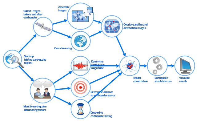
This work flow chart sample was redesigned from the picture "Simulation for earthquake disaster assessment" from the article "Simulation Workflows".
[iaas.uni-stuttgart.de/ forschung/ projects/ simtech/ sim-workflows.php]
" This simulation was developed to have an in depth understanding of the destructions and the decisions to be made in various phases of crisis management (Source: Mahdi Hashemi and Ali A. Alesheikh (2010). "Developing an agent based simulation model for earthquakes in the context of SDI." GSDI 12 World Conference. 19 – 22 October 2010. Singapour). The simulation process contains following major steps:
(1) All spatial information including satellite images (before and after the earthquake) and topographic/ cadastral maps of the area are mosaicked and georeferenced. The parts of the city that contain various levels of destructions are selected. Three types of features namely buildings, roads and recreational areas are classified and extracted from the satellite images.
(2) The governing factors of destructions are identified; a mathematical model that integrates the factors is constructed.
(3) The simulation is constructed for various parameter values (different earthquake strength, time elapses, etc.)" [iaas.uni-stuttgart.de/ forschung/ projects/ simtech/ sim-workflows.php]
The example "Workflow diagram - Earthquake disaster assessment" was drawn using the ConceptDraw PRO diagramming and vector drawing software extended with the Workflow Diagrams solution from the Business Processes area of ConceptDraw Solution Park.
Work flow chart
- Basic Flowchart Symbols and Meaning | Road Transport - Design ...
- UML Class Diagram Generalization Example UML Diagrams | Basic ...
- Basic Flowchart Symbols and Meaning | Process Flowchart | Design ...
- Basic Flowchart Symbols and Meaning | Road Transport - Design ...
- Flow chart Example. Warehouse Flowchart | Road Transport ...
- Road Transport - Design Elements | Flow chart Example ...
- Sales Process Flowchart . Flowchart Examples | Sales Process ...
- Basic Flowchart Symbols and Meaning | UML Class Diagram ...
- Flow chart Example. Warehouse Flowchart | Spatial infographics ...
- Basic Flowchart Symbols and Meaning | Road Transport - Design ...
- Basic Flowchart Symbols and Meaning | Road signs - Vector stencils ...
- Process Flowchart | Design elements - Industrial equipment | Road ...
- Road Transport - Design Elements | Basic Flowchart Symbols and ...
- Basic Flowchart Symbols and Meaning | Vehicular Networking ...
- Process Flowchart | Road Transport - Design Elements | Event ...
- Road signs - Vector stencils library | Basic Flowchart Symbols and ...
- Spatial infographics Design Elements: Transport Map | Flow chart ...
- UML Class Diagram Generalization Example UML Diagrams | Road ...
- Transport Flowchart
- 3D pictorial road map | Flow chart Example. Warehouse Flowchart ...