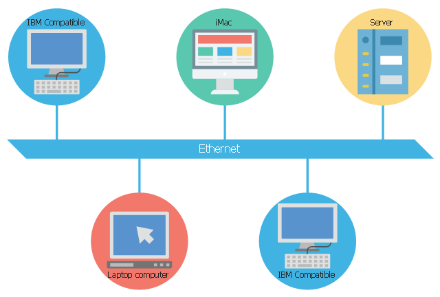
This concept diagram sample shows the local area network using 10BASE5 Ethernet. It was designed on the base of Wikimedia Commons file: Ethernet LAN.svg.
[commons.wikimedia.org/ wiki/ File:Ethernet_ LAN.svg]
This file is licensed under the Creative Commons Attribution-Share Alike 4.0 International license. [creativecommons.org/ licenses/ by-sa/ 4.0/ deed.en]
"A local area network (LAN) is a computer network that interconnects computers within a limited area such as a residence, school, laboratory, university campus or office building and has its network equipment and interconnects locally managed. By contrast, a wide area network (WAN), not only covers a larger geographic distance, but also generally involves leased telecommunication circuits or Internet links.
Ethernet and Wi-Fi are the two most common transmission technologies in use for local area networks." [Local area network. Wikipedia]
The LAN diagram example "Ethernet network" was created using the ConceptDraw PRO diagramming and vector drawing software extended with the Computers and Communications solution from the Illustration area of ConceptDraw Solution Park.
LAN diagram
Local area network (LAN). Computer and Network Examples
 diagram")

 Network Layout Floor Plans
Network Layout Floor Plans solution extends ConceptDraw DIAGRAM software functionality with powerful tools for quick and efficient documentation the network equipment and displaying its location on the professionally designed Network Layout Floor Plans. Never before creation of Network Layout Floor Plans, Network Communication Plans, Network Topologies Plans and Network Topology Maps was not so easy, convenient and fast as with predesigned templates, samples, examples and comprehensive set of vector design elements included to the Network Layout Floor Plans solution. All listed types of plans will be a good support for the future correct cabling and installation of network equipment.
Network wiring cable. Computer and Network Examples

How To use Switches in Network Diagram

ATM Network. Computer and Network Examples

Network Hubs

Daisy Chain Network Topology

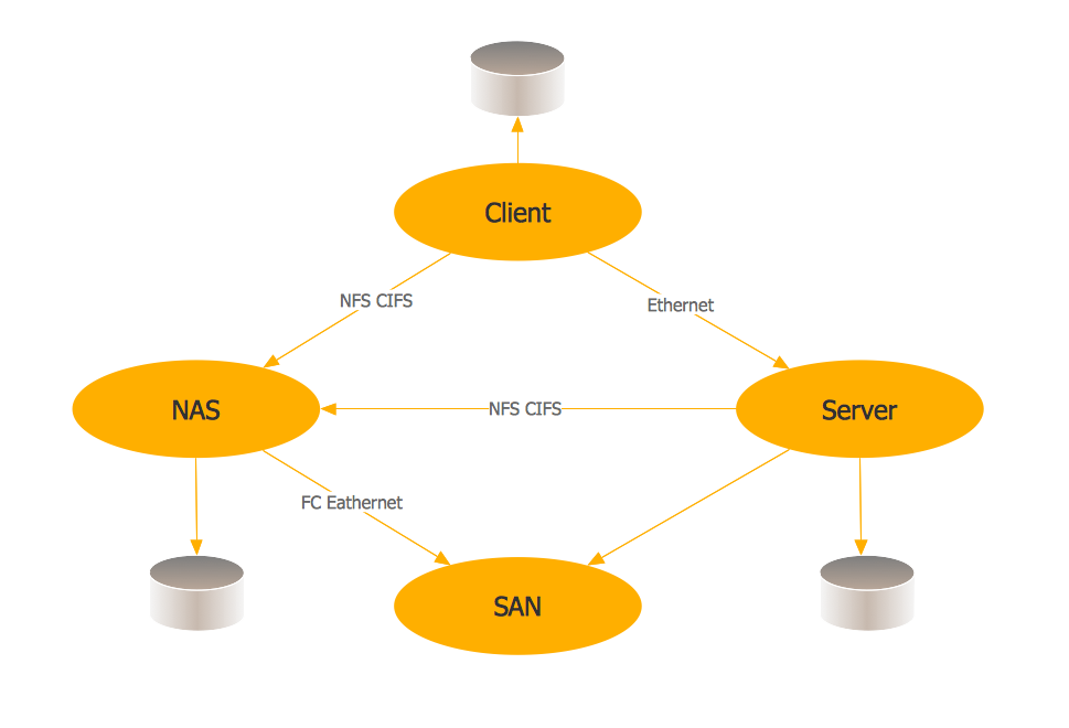
Storage area networks (SAN). Computer and Network Examples
Wireless Network Topology

- Ethernet network | Ethernet local area network layout floor plan ...
- Diagram An Ethernet Network
- Ethernet network | Network Glossary Definition | Draw Geographical ...
- Ethernet Lan Diagram
- Laboratory equipment - Vector stencils library | Ethernet network ...
- Ethernet cable layout | Ethernet local area network layout floor plan ...
- Network Layout Floor Plans | Local area network ( LAN ). Computer ...
- Design elements - Network layout floorplan | Network Protocols ...
- Healthcare Illustration
- Wireless router network diagram | What Is a Wireless Network ...