ConceptDraw DIAGRAM ER Diagram Tool

"Chen's notation for entity–relationship modeling uses rectangles to represent entity sets, and diamonds to represent relationships appropriate for first-class objects: they can have attributes and relationships of their own. If an entity set participates in a relationship set, they are connected with a line.
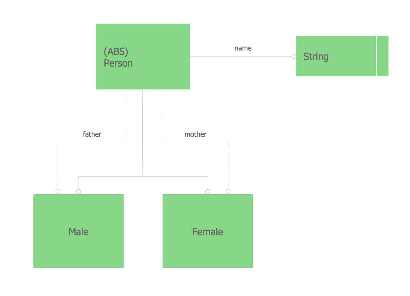
Attributes are drawn as ovals and are connected with a line to exactly one entity or relationship set.
Cardinality constraints are expressed as follows:
- a double line indicates a participation constraint, totality or surjectivity: all entities in the entity set must participate in at least one relationship in the relationship set;
- an arrow from entity set to relationship set indicates a key constraint, i.e. injectivity: each entity of the entity set can participate in at most one relationship in the relationship set;
- a thick line indicates both, i.e. bijectivity: each entity in the entity set is involved in exactly one relationship.
- an underlined name of an attribute indicates that it is a key: two different entities or relationships with this attribute always have different values for this attribute.
Attributes are often omitted as they can clutter up a diagram; other diagram techniques often list entity attributes within the rectangles drawn for entity sets." [Entity–relationship model. Wikipedia]
The vector stencils library ERD, Chen's notation contains 13 symbols for drawing entity-relatinship diagrams using the ConceptDraw PRO diagramming and vector drawing software.
The example "Design elements - ER diagram (Chen notation)" is included in the Entity-Relationship Diagram (ERD) solution from the Software Development area of ConceptDraw Solution Park.
Chen's ERD
.png--diagram-flowchart-example.png)
UML Class Diagram Notation

UML Class Diagram Generalization Example UML Diagrams

Martin ERD Diagram

Data Flow Diagrams

 Entity-Relationship Diagram (ERD)
An Entity-Relationship Diagram (ERD) is a visual presentation of entities and relationships. That type of diagrams is often used in the semi-structured or unstructured data in databases and information systems. At first glance ERD is similar to a flowch
JSD - Jackson system development

Express-G Diagram
UML Deployment Diagram. Design Elements

- Cardinality Constraints Er Diagram
- Entity Relationship Diagram Symbols | ERD Symbols and Meanings ...
- UML Class Diagram Notation | Design elements - ERD (crow's foot ...
- Chen Notation | Design elements - ER diagram (Chen notation ...
- Crow's Foot Notation | Design elements - ER diagram (Chen ...
- Design elements - ERD (crow's foot notation ) | Design elements - ER ...
- Design elements - ER diagram (Chen notation ) | Design elements ...
- Design elements - ER diagram (Chen notation ) | Crow's foot ERD ...
- Design elements - ER diagram (Chen notation ) | Chen Notation ...