Process Flowchart


Basic Flowchart Symbols and Meaning


Mechanical Drawing Symbols

Accounting Flowchart Symbols

Electrical Symbols — Switches and Relays

UML Class Diagram Notation

Electrical Symbols — Logic Gate Diagram

Process Engineering
Process Diagrams
Electrical Symbols, Electrical Schematic Symbols

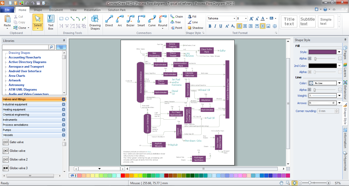
The vector stencils library "Chemical engineering" contains 24 symbols of chemical and process engineering equipment.
Use these shapes for drawing block flow diagrams (BFD), process flow diagrams (PFD), piping and instrumentation diagrams (P&ID), and water flow diagrams.
"Chemical engineering is a branch of engineering that applies the natural (or experimental) sciences (e.g., chemistry and physics) and life sciences (e.g. biology, microbiology and biochemistry) together with mathematics and economics to production, transformation, transportation and proper usage of chemicals, materials and energy. It essentially deals with the engineering of chemicals, energy and the processes that create and/ or convert them. Modern chemical engineers are concerned with processes that convert raw-materials or (cheap)chemicals into more useful or valuable forms. In addition, they are also concerned with pioneering valuable materials and related techniques – which are often essential to related fields such as nanotechnology, fuel cells and bioengineering. Within chemical engineering, two broad subgroups include design, manufacture, and operation of plants and machinery in industrial chemical and related processes ("chemical process engineers") and development of new or adapted substances for products ranging from foods and beverages to cosmetics to cleaners to pharmaceutical ingredients, among many other products ("chemical product engineers")." [Chemical engineering. Wikipedia]
The example "Design elements - Chemical engineering" was created using the ConceptDraw PRO diagramming and vector drawing software extended with the Chemical and Process Engineering solution from the Engineering area of ConceptDraw Solution Park.
Chemical engineering symbols

The vector stencils library "Switches and relays" contains 58 symbols of electrical contacts, switches, relays, circuit breakers, selectors, connectors, disconnect devices, switching circuits, current regulators, and thermostats for electrical devices.
"In electrical engineering, a switch is an electrical component that can break an electrical circuit, interrupting the current or diverting it from one conductor to another.
The most familiar form of switch is a manually operated electromechanical device with one or more sets of electrical contacts, which are connected to external circuits. Each set of contacts can be in one of two states: either "closed" meaning the contacts are touching and electricity can flow between them, or "open", meaning the contacts are separated and the switch is nonconducting. The mechanism actuating the transition between these two states (open or closed) can be either a "toggle" (flip switch for continuous "on" or "off") or "momentary" (push-for "on" or push-for "off") type.
A switch may be directly manipulated by a human as a control signal to a system, such as a computer keyboard button, or to control power flow in a circuit, such as a light switch. Automatically operated switches can be used to control the motions of machines, for example, to indicate that a garage door has reached its full open position or that a machine tool is in a position to accept another workpiece. Switches may be operated by process variables such as pressure, temperature, flow, current, voltage, and force, acting as sensors in a process and used to automatically control a system. ... A switch that is operated by another electrical circuit is called a relay. Large switches may be remotely operated by a motor drive mechanism. Some switches are used to isolate electric power from a system, providing a visible point of isolation that can be padlocked if necessary to prevent accidental operation of a machine during maintenance, or to prevent electric shock." [Switch. Wikipedia]
"A relay is an electrically operated switch. Many relays use an electromagnet to mechanically operate a switch, but other operating principles are also used, such as solid-state relays. Relays are used where it is necessary to control a circuit by a low-power signal (with complete electrical isolation between control and controlled circuits), or where several circuits must be controlled by one signal. The first relays were used in long distance telegraph circuits as amplifiers: they repeated the signal coming in from one circuit and re-transmitted it on another circuit. Relays were used extensively in telephone exchanges and early computers to perform logical operations.
A type of relay that can handle the high power required to directly control an electric motor or other loads is called a contactor. Solid-state relays control power circuits with no moving parts, instead using a semiconductor device to perform switching. Relays with calibrated operating characteristics and sometimes multiple operating coils are used to protect electrical circuits from overload or faults; in modern electric power systems these functions are performed by digital instruments still called "protective relays"." [Relay. Wikipedia]
The shapes example "Design elements - Switches and relays" was drawn using the ConceptDraw PRO diagramming and vector drawing software extended with the Electrical Engineering solution from the Engineering area of ConceptDraw Solution Park.
Switch and relay symbols

Types of Flowcharts


Business Process Flowchart Symbols

Sales Process Flowchart Symbols

- Mechanical Engineering Operations Pdf Symbol
- Mechanical Operation Symbol
- Operations Symbol In Mechanical Engineering
- Operation Symbols For Mechanical Engineering
- Symbol For Mechanical Operations
- Mechanical Drawing Symbols | Mechanical Engineering | Process ...
- Mechanical Engineering Drawing Operations Symbols
- Mechanical Operations And Symbol In Pdf
- Mechanical Engineering Symbols Of Operation
- Mechanical Drawing Symbols | Mechanical Engineering ...
- Operation Symbols In Industrial Engineering
- Operation Symbol Of Mechanical
- Mechanical Operation Symbols
- Industrial Engineering Flowchart Symbols
- Unit Operations Symbols On Engineering Drawing
- Unit Operation Symbol
- Symbol Of Mechanical Operations
- Mechanical Operation Drawing Symbols
- Chemical Engineering | Chemical and Process Engineering ...
- Symbol Of Mechanical Operation