Mechanical Drawing Symbols

Retract resistor check valve application: pneumatic cylinder, piston driven by Compressed air through 2 Retract resistor check valves.
"A check valve, clack valve, non-return valve or one-way valve is a valve that normally allows fluid (liquid or gas) to flow through it in only one direction.
Check valves are two-port valves, meaning they have two openings in the body, one for fluid to enter and the other for fluid to leave. There are various types of check valves used in a wide variety of applications. Check valves are often part of common household items. Although they are available in a wide range of sizes and costs, check valves generally are very small, simple, or inexpensive. Check valves work automatically and most are not controlled by a person or any external control; accordingly, most do not have any valve handle or stem. The bodies (external shells) of most check valves are made of plastic or metal.
An important concept in check valves is the cracking pressure which is the minimum upstream pressure at which the valve will operate. Typically the check valve is designed for and can therefore be specified for a specific cracking pressure.
Heart valves are essentially inlet and outlet check valves for the heart ventricles, since the ventricles act as pumps." [Check valve. Wikipedia]
This hydraulic schematic example was redrawn using ConceptDraw PRO diagramming and vector drawing software from the Wikimedia Commons file: Retract resistor check valve application.png.
[commons.wikimedia.org/ wiki/ File:Retract_ resistor_ check_ valve_ application.png]
The hydraulic engineering drawing example "Retract resistor check valve application" was created using the ConceptDraw PRO diagramming and vector drawing software extended with the Mechanical Engineering solution from the Engineering area of ConceptDraw Solution Park.
Hydraulic schematic

The vector stencils library "Valve assembly" contains 141 symbols of pressure and flow regulators, flow direction indicators, controls, and symbols to design flow paths of control valves in fluid power systems.
Use these valve assembly shapes to design the engineering drawings of hydraulic and pneumatic valve assemblies
in the ConceptDraw PRO diagramming and vector drawing software extended with the Mechanical Engineering solution from the Engineering area of ConceptDraw Solution Park.
www.conceptdraw.com/ solution-park/ engineering-mechanical
2 position 2,3,4 port (fin. pos.)
-valve-assembly---vector-stencils-library.png--diagram-flowchart-example.png)
2 position 2,3,4 port (infin. pos.)
-valve-assembly---vector-stencils-library.png--diagram-flowchart-example.png)
2 position 2,3,4 port (ext., fin.pos.)
-valve-assembly---vector-stencils-library.png--diagram-flowchart-example.png)
2 position 2,3,4 port (ext., infin. pos.)
-valve-assembly---vector-stencils-library.png--diagram-flowchart-example.png)
2 position 5 port (fin. pos.)
-valve-assembly---vector-stencils-library.png--diagram-flowchart-example.png)
2 position 5 port (infin. pos.)
-valve-assembly---vector-stencils-library.png--diagram-flowchart-example.png)
2 position 5 port (ext., fin.pos.)
-valve-assembly---vector-stencils-library.png--diagram-flowchart-example.png)
2 position 5 port (ext., infin. pos.)
-valve-assembly---vector-stencils-library.png--diagram-flowchart-example.png)
3 position 2,3,4 port (fin. pos.)
-valve-assembly---vector-stencils-library.png--diagram-flowchart-example.png)
3 position 2,3,4 port (infin. pos.)
-valve-assembly---vector-stencils-library.png--diagram-flowchart-example.png)
3 position 2,3,4 port (ext., fin.pos.)
-valve-assembly---vector-stencils-library.png--diagram-flowchart-example.png)
3 position 2,3,4 port (ext., infin. pos.)
-valve-assembly---vector-stencils-library.png--diagram-flowchart-example.png)
3 position 5 port (fin. pos.)
-valve-assembly---vector-stencils-library.png--diagram-flowchart-example.png)
3 position 5 port (infin. pos.)
-valve-assembly---vector-stencils-library.png--diagram-flowchart-example.png)
3 position 5 port (ext., fin.pos.)
-valve-assembly---vector-stencils-library.png--diagram-flowchart-example.png)
3 position 5 port (ext., infin. pos.)
-valve-assembly---vector-stencils-library.png--diagram-flowchart-example.png)
4 position 2,3,4 port (fin. pos.)
-valve-assembly---vector-stencils-library.png--diagram-flowchart-example.png)
4 position 2,3,4 port (infin. pos.)
-valve-assembly---vector-stencils-library.png--diagram-flowchart-example.png)
4 position 2,3,4 port (ext., fin.pos.)
-valve-assembly---vector-stencils-library.png--diagram-flowchart-example.png)
4 position 2,3,4 port (ext., infin. pos.)
-valve-assembly---vector-stencils-library.png--diagram-flowchart-example.png)
4 position 5 port (fin. pos.)
-valve-assembly---vector-stencils-library.png--diagram-flowchart-example.png)
4 position 5 port (infin. pos.)
-valve-assembly---vector-stencils-library.png--diagram-flowchart-example.png)
4 position 5 port (ext., fin.pos.)
-valve-assembly---vector-stencils-library.png--diagram-flowchart-example.png)
4 position 5 port (ext., infin. pos.)
-valve-assembly---vector-stencils-library.png--diagram-flowchart-example.png)
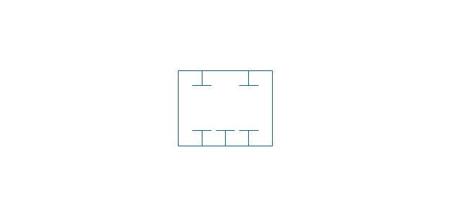
Box 5 port

Box 2,3,4 port

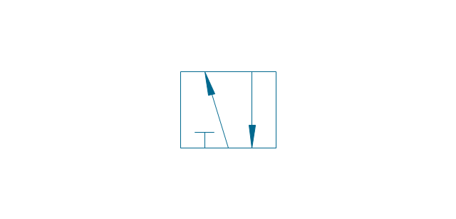
2-port, pneum., 1 arrow
2-port, pneum., 2 arrows

2-port, hydr., 1 arrow
2-port, hydr., 2 arrows

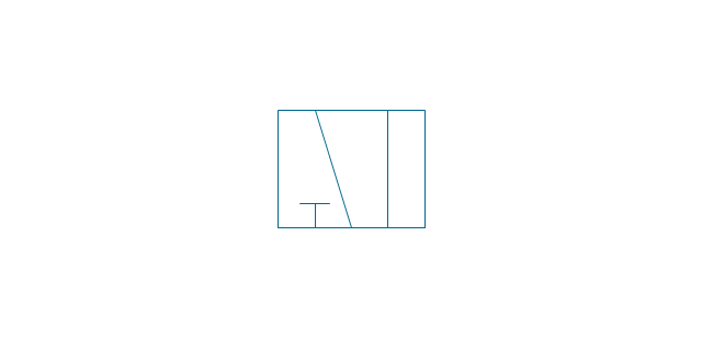
2-port

2-port closed

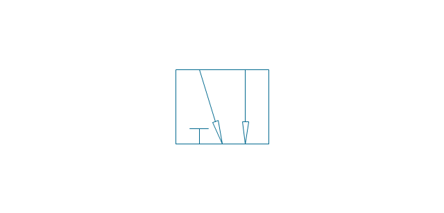
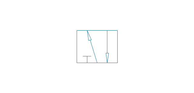
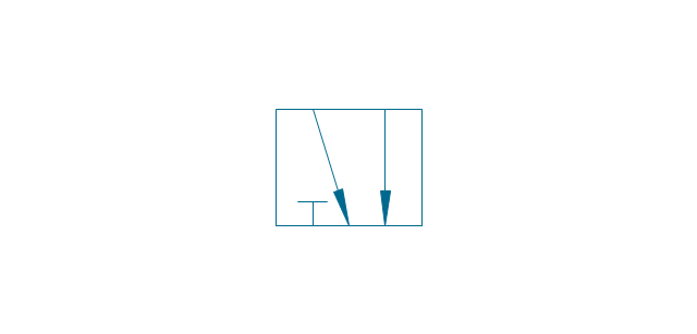
3-port, pneum., 1 arrow
3-port, pneum., 2 arrows
3-port, hydr., 1 arrow
3-port, hydr., 2 arrows
3-port
3-port crossover, pneum., 1 arrow
3-port crossover, pneum., 2 arrows
3-port crossover, hydr., 1 arrow
3-port crossover, hydr., 2 arrows

3-port crossover

4-port, pneum.
4-port, hydr.
4-port closed
4-port crossed, pneum.

4-port crossed, hydr.

4-port tandem, pneum., 1 arrow
4-port tandem, pneum., 2 arrows
4-port tandem, hydr., 1 arrow
4-port tandem, hydr., 2 arrows
4-port tandem
4-port open
4-port semi-connected
4-port crossover, pneum., 1 arrow
4-port crossover, pneum., 2 arrows
4-port crossover, hydr., 1 arrow
4-port crossover, hydr., 2 arrows
4-port crossover
5-port, pneum., arrows same
5-port, pneum., arrows opposite
5-port, hydr., arrows same
5-port, hydr., arrows opposite
5-port
5-port closed
5-port crossover, pneum., arrows same
5-port crossover, pneum., arrows opposite
5-port crossover, hydr., arrows same
5-port crossover, hydr., arrows opposite
5-port crossover
Spring

Spring, var.

Plunger

Plunger, var.
Roller

Roller (arrow)
-valve-assembly---vector-stencils-library.png--diagram-flowchart-example.png)
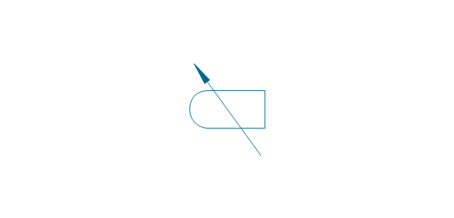
One-way trip
One-way trip (arrow)
-valve-assembly---vector-stencils-library.png--diagram-flowchart-example.png)
Manual override

Pull button

Push button

Pull/push button

Lever
Pedal

Treadle

Electric rotor
Electric control, proportional, 1 winding
Electric control, proportional, 2 windings

Electric control, non-proportional, 1 winding

Electric control, non-proportional, 2 windings

Pilot-operated, pneum., 1 arrow, points left

Pilot-operated, pneum., 1 arrow, points right

Pilot-operated, pneum., 2 arrows, points left

Pilot-operated, pneum., 2 arrows, points right

Pilot-operated, pneum.

Pilot-operated, hydr., 1 arrow, points left

Pilot-operated, hydr., 1 arrow, points right

Pilot-operated, hydr., 2 arrows, points left

Pilot-operated, hydr., 2 arrows, points right

Pilot-operated, hydr.

Detent

Junction dot

T-junction, con.

T-junction, discon.

4-way junction, con.
4-way junction, discon.

Crossing
Flexible line
Air bleed, continuous

Air bleed, temporary

Fluid energy

Fluid energy, hydr.

Fluid energy, pneum.

Air exhaust port

Fluid flow, pneum.
Fluid flow, hydr.

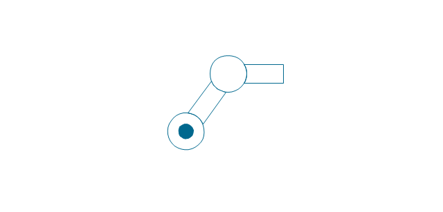
Rotary connection (1)
-valve-assembly---vector-stencils-library.png--diagram-flowchart-example.png)
Rotary connection (3)
-valve-assembly---vector-stencils-library.png--diagram-flowchart-example.png)
Variable arrow
Curved arrow, top

Curved arrow, bottom

Curved arrow, both ends

Flow path

Flow path, pneum., 1 arrow
Flow path, hydr., 1 arrow
Flow path, pneum., 2 arrows

Flow path, hydr., 2 arrows

Shaft, top arrow
Shaft, bottom arrow
Shaft, both arrows

Shaft

Rod, right arrow
Rod, left arrow
Rod, both arrows

Over - center

Latch
Closed path

Electric

Restriction

Closed path (double)
-valve-assembly---vector-stencils-library.png--diagram-flowchart-example.png)
Temperature

The vector stencils library "Valves and fittings" contains 104 symbols of valve components.
Use these icons for drawing industrial piping systems; process, vacuum, and fluids piping; hydraulics piping; air and gas piping; materials distribution; and liquid transfer systems in the ConceptDraw PRO software extended with the Chemical and Process Engineering solution from the Chemical and Process Engineering area of ConceptDraw Solution Park.
www.conceptdraw.com/ solution-park/ engineering-chemical-process
Electrically bonded

Bursting disc

Flame arrester

Strainer

Separator

Exhaust silencer

Bell mouth

Exhaust head

Hydrant

Drain silencer

Liquid seal open/closed

Y strainer

Gate valve

Globe valve

Globe valve 2

Globe valve 3

Screw-down valve

Lock-shield valve

Reel valve

Check valve

Check valve 2

Check valve 3

Screw-down check valve

Stop check valve

Diaphragm valve

Diaphragm valve 2

Diaphragm valve 3

Powered valve

Powered valve 2

Powered valve 3

Needle valve

Needle valve 2

Needle valve 3

Relief valve

Relief valve 2

Relief valve 3

Angle valve

Angle valve 2

Angle valve 3

Angle valve 4

Float operated valve

Float operated valve 2

Flanged valve

Butterfly valve

Butterfly valve 2

Wedge gate valve

Parallel slide valve

Ball valve

Ball valve 2

Ball valve 3

Relief angle valve vacuum

Relief angle valve pressure

Reducing valve

Reducing valve 2

Plug valve 3 way

Plug valve L point

Plug valve 2

Plug valve

Plug valve straight through

Plug valve T point

3-way plug valve

3-way plug valve 2

3-way plug valve 3

Mixing valve

Valve Manifold

Characterized port valve

Reducer

Reducer 2

General joint

Butt weld

Butt weld 2

Butt weld 3

Butt weld 4

Flanged/ bolted

Soldered / solvent

Soldered / solvent 2

Screwed joint

Screwed joint 2

Screwed joint 3

Socket and spigot

Socket and spigot 2

Socket and spigot 3

Sleeve

Sleeve 2

Screwed sleeve

Screwed sleeve 2

Socket weld

Socket weld 2

Swivel joint

Swivel joint 2

Swivel joint 3

End cap

End cap butt welded

End cap screwed

End cap socket and spigot

End cap fillet welded

End cap screwed and plugged

End cap quick release

End cap flanged and bolted

End cap flanged and bolted 2

Electrically insulated

Tundish

Syphon drain

Open vent

How to Draw a Flowchart
 Plumbing and Piping Plans
Plumbing and Piping Plans solution extends ConceptDraw DIAGRAM.2.2 software with samples, templates and libraries of pipes, plumbing, and valves design elements for developing of water and plumbing systems, and for drawing Plumbing plan, Piping plan, PVC Pipe plan, PVC Pipe furniture plan, Plumbing layout plan, Plumbing floor plan, Half pipe plans, Pipe bender plans.
The vector stencils library "Valves" contains 91 symbols of valves. Use it for drawing plumbing and piping plans, schematic diagrams and blueprints of industrial piping systems; process, vacuum, and fluids piping; hydraulics piping; air and gas piping; materials distribution; and liquid transfer systems in the ConceptDraw PRO diagramming and vector drawing software extended with the Plumbing and Piping Plans solution from the Building Plans area of ConceptDraw Solution Park.
In-line valve

3-way valve

4-way valve

Screw-down valve

Lock-shield valve

Reel valve

Relief valve

Relief valve 2

Relief valve 3

Relief valve 4

Angle valve

Angle valve 2

Angle valve 3

Angle valve 4

Check valve

Check valve 2

Screwdown valve

Float operated valve

Float operated valve 2

Flanged valve

Flanged valve 2

Butterfly valve

Butterfly valve 2

Globe valve

Globe valve 2

Globe valve 3

Needle valve

Needle valve 2

Needle valve 3

Needle valve 4

Diaphragm valve

Diaphragm valve 2

Diaphragm valve 3

Wedge gate valve

Parallel side valve

Gate valve

Ball valve

Ball valve 2

Ball valve 3

Powered control valve

Powered control valve 2

Powered control valve 3

Relief angle valve, pressure

Relief angle valve, vacuum

Reducing valve

Reducing valve 2

Plug valve

Plug valve 2

Plug valve, straight through

3-way plug valve

Plug valve, T-port

Plug valve, L-port

3-way plug valve

3-way plug valve 2

3-way plug valve 3

3-way plug valve, T-port

3-way plug valve, L-port

Mixing valve

Characterized port valve

Manual isolation

Power signal

Statically loaded

Spring loaded

Spring loaded 2

Remote control

Diaphragm

Diaphragm, positioner

Chain operated

Gear operated

Solenoid

Weight loaded

Weight loaded 2

Weight loaded 3

Float operated

Float operated 2

Dash-pot

Dash-pot 2

Piston

Quick opening

Quick opening 2

Quick closing

Quick closing 2

Connecting unit

Connecting unit 2

Connecting unit 3

Motor element

Motor element, opens on failure

Motor element, closes on failure

Motor element, retains position on fail

Motor element, safe direction

Regulating

Accounting Flowchart Symbols

The vector stencils library "Workflow diagrams" contains 54 symbol icons of workflow diagrams.
The workflow diagrams represent information flow, automation of business processes, business process re-engineering, accounting, management, and human resources tasks in industry, business, and manufacturing.
Use this library to draw workflow diagrams in the ConceptDraw PRO diagramming and vector drawing software extended with the Workflow Diagrams solution from the Business Processes area of ConceptDraw Solution Park.
www.conceptdraw.com/ solution-park/ business-process-workflow-diagrams
Accounting

Accounts Payable
Accounts Receivable
Bank

Board of Directors

Copy Center
Customer Service

Distribution
Finance

Information Systems

International Division

International Marketing

International Sales

Inventory
Legal Department
Mailroom 2

Mailroom 1

Management
Manufacturing

Marketing

Motor Pool

Packaging

Payroll

Person 1

Person 2

Personnel/ Staff

Publications

Purchasing

Quality Assurance

Exchange

Reception

Research and Development

Sale contract

Shipping

Suppliers

Telecommunications

Treasurer
Warehouse
Lorry

Quality

Production
Box
Boxes
Open box

Payment

Receiving
Sales

Phone
Operator 1

Online booking

Operator 2

Server
Car

Mini truck
- Mechanical Engineering | Pneumatic 5-ported 3-position valve ...
- Design elements - Pneumatic pumps and motors | Pneumatic 5 ...
- Mechanical Drawing Symbols | Design elements - Fluid power ...
- Mechanical Drawing Symbols | Pneumatic 5-ported 3-position valve ...
- Typical Hydraulic Cylinder Control Schematic
- Mechanical Engineering Drawing Symbol For A Spring
- Mechanical Drawing Software | Pneumatic 5-ported 3-position valve ...
- Engg Drawing Symbol Of Drain Cock
- How To Draw Hydraulics Circuit Diagrams
- Mechanical Engineering | Technical drawing - Machine parts ...