Electrical Symbols, Electrical Diagram Symbols

Wiring Diagrams with ConceptDraw DIAGRAM

The vector stencils library "Delay elements" contains 12 symbols of delay elements for drawing electrical schematics and electronic circuit diagrams.
"An analog delay line is a network of electrical components connected in series, where each individual element creates a time difference or phase change between its input signal and its output signal. It operates on analog signals whose amplitude varies continuously. An example is a bucket-brigade device. Other types of delay line include acoustic, magnetostrictive, and surface acoustic wave devices. A series of RC networks can be cascaded to form a delay. A long transmission line can also provide a delay element. The delay time of an analog delay line may be only a few nanoseconds or several milliseconds, limited by the practical size of the physical medium used to delay the signal and the propagation speed of impulses in the medium." [Analog delay line. Wikipedia]
The symbols example "Design elements - Delay elements" was drawn using the ConceptDraw PRO diagramming and vector drawing software extended with the Electrical Engineering solution from the Engineering area of ConceptDraw Solution Park.
Delay element symbols

The vector stencils library "Semiconductor diodes" contains 24 symbols of semiconductor diodes for drawing electronic schematics and circuit diagrams.
"In electronics, a diode is a two-terminal electronic component with asymmetric conductance; it has low (ideally zero) resistance to current in one direction, and high (ideally infinite) resistance in the other. A semiconductor diode, the most common type today, is a crystalline piece of semiconductor material with a p–n junction connected to two electrical terminals. A vacuum tube diode has two electrodes, a plate (anode) and a heated cathode. Semiconductor diodes were the first semiconductor electronic devices. ...
Today, most diodes are made of silicon, but other semiconductors such as selenium or germanium are sometimes used." [Diode. Wikipedia]
The shapes example "Design elements - Semiconductor diodes" was drawn using the ConceptDraw PRO diagramming and vector drawing software extended with the Electrical Engineering solution from the Engineering area of ConceptDraw Solution Park.
Semiconductor diode symbols

The vector stencils library "Electrical circuits" contains 49 element symbols of electrical and electronic devices, including ignitors, starters, transmitters, circuit protectors, transducers, radio and audio equipment.
Use it for drawing electronic circuit diagrams and electrical schematics.
"An electrical network is an interconnection of electrical elements such as resistors, inductors, capacitors, voltage sources, current sources and switches. An electrical circuit is a network consisting of a closed loop, giving a return path for the current. Linear electrical networks, a special type consisting only of sources (voltage or current), linear lumped elements (resistors, capacitors, inductors), and linear distributed elements (transmission lines), have the property that signals are linearly superimposable. They are thus more easily analyzed, using powerful frequency domain methods such as Laplace transforms, to determine DC response, AC response, and transient response.
A resistive circuit is a circuit containing only resistors and ideal current and voltage sources. Analysis of resistive circuits is less complicated than analysis of circuits containing capacitors and inductors. If the sources are constant (DC) sources, the result is a DC circuit.
A network that contains active electronic components is known as an electronic circuit. Such networks are generally nonlinear and require more complex design and analysis tools." [Electrical network. Wikipedia]
The symbils example "Design elements - Electrical circuits" was drawn using the ConceptDraw PRO diagramming and vector drawing software extended with the Electrical Engineering solution from the Engineering area of ConceptDraw Solution Park.
Electrical circuit elements

The vector stencils library "Terminals and connectors" contains 43 element symbols of terminals, connectors, plugs, polarized connectors, jacks, coaxial cables, and conductors.
Use it for drawing the wiring diagrams, electrical layouts, electronic schematics, and circuit diagrams.
"An electrical connector is an electro-mechanical device for joining electrical circuits as an interface using a mechanical assembly. Connectors consist of plugs (male-ended) and jacks (female-ended). The connection may be temporary, as for portable equipment, require a tool for assembly and removal, or serve as a permanent electrical joint between two wires or devices. An adapter can be used to effectively bring together dissimilar connectors.
There are hundreds of types of electrical connectors. Connectors may join two lengths of flexible copper wire or cable, or connect a wire or cable or optical interface to an electrical terminal.
In computing, an electrical connector can also be known as a physical interface... Cable glands, known as cable connectors in the US, connect wires to devices mechanically rather than electrically and are distinct from quick-disconnects performing the latter." [Electrical connector. Wikipedia]
"A terminal is the point at which a conductor from an electrical component, device or network comes to an end and provides a point of connection to external circuits. A terminal may simply be the end of a wire or it may be fitted with a connector or fastener. In network analysis, terminal means a point at which connections can be made to a network in theory and does not necessarily refer to any real physical object. In this context, especially in older documents, it is sometimes called a "pole".
The connection may be temporary, as seen in portable equipment, may require a tool for assembly and removal, or may be a permanent electrical joint between two wires or devices.
All electric cell have two terminals. The first is the positive terminal and the second is the negative terminal. The positive terminal looks like a metal cap and the negative terminal looks like a metal disc. The current flows from the positive terminal, and out through the negative terminal, replicative of current flow (positive (+) to negative (-) flow)." [Terminal (electronics). Wikipedia]
The shapes example "Design elements - Terminals and connectors" was drawn using the ConceptDraw PRO diagramming and vector drawing software extended with the Electrical Engineering solution from the Engineering area of ConceptDraw Solution Park.
Terminal and connector symbols

The vector stencils library "Semiconductors" contains 22 symbols of rectifiers, diodes, charge transfer and electronic conduction devices, switches, cathodes, transistors, thyristors, and transceivers for semiconductor (SIS) design.
"Semiconductor devices are electronic components that exploit the electronic properties of semiconductor materials, principally silicon, germanium, and gallium arsenide, as well as organic semiconductors. Semiconductor devices have replaced thermionic devices (vacuum tubes) in most applications. They use electronic conduction in the solid state as opposed to the gaseous state or thermionic emission in a high vacuum.
Semiconductor devices are manufactured both as single discrete devices and as integrated circuits (ICs), which consist of a number - from a few (as low as two) to billions - of devices manufactured and interconnected on a single semiconductor substrate, or wafer. ...
All transistor types can be used as the building blocks of logic gates, which are fundamental in the design of digital circuits. In digital circuits like microprocessors, transistors act as on-off switches; in the MOSFET, for instance, the voltage applied to the gate determines whether the switch is on or off.
Transistors used for analog circuits do not act as on-off switches; rather, they respond to a continuous range of inputs with a continuous range of outputs. Common analog circuits include amplifiers and oscillators.
Circuits that interface or translate between digital circuits and analog circuits are known as mixed-signal circuits.
Power semiconductor devices are discrete devices or integrated circuits intended for high current or high voltage applications. Power integrated circuits combine IC technology with power semiconductor technology, these are sometimes referred to as "smart" power devices. Several companies specialize in manufacturing power semiconductors." [Semiconductor device. Wikipedia]
The shapes example "Design elements - Semiconductors" was drawn using the ConceptDraw PRO diagramming and vector drawing software extended with the Electrical Engineering solution from the Engineering area of ConceptDraw Solution Park.
Semiconductor elements

The vector stencils library "Resistors" contains 14 element symbols of resistors for drawing electronic schematics, circuit diagrams and electrical drawings.
"A resistor is a passive two-terminal electrical component that implements electrical resistance as a circuit element. Resistors act to reduce current flow, and, at the same time, act to lower voltage levels within circuits. Resistors may have fixed resistances or variable resistances, such as those found in thermistors, varistors, trimmers, photoresistors and potentiometers.
The current through a resistor is in direct proportion to the voltage across the resistor's terminals. This relationship is represented by Ohm's law ...
Resistors are common elements of electrical networks and electronic circuits and are ubiquitous in electronic equipment. Practical resistors can be composed of various compounds and films, as well as resistance wires (wire made of a high-resistivity alloy, such as nickel-chrome). Resistors are also implemented within integrated circuits, particularly analog devices, and can also be integrated into hybrid and printed circuits." [Resistor. Wikipedia]
The shapes example "Design elements - Resistors" was drawn using the ConceptDraw PRO diagramming and vector drawing software extended with the Electrical Engineering solution from the Engineering area of ConceptDraw Solution Park.
Resistor symbols

The vector stencils library "Inductors" contains 41 symbols of inductor elements for drawing electronic circuit diagrams.
"An inductor, also called a coil or reactor, is a passive two-terminal electrical component which resists changes in electric current passing through it. It consists of a conductor such as a wire, usually wound into a coil. When a current flows through it, energy is stored temporarily in a magnetic field in the coil. When the current flowing through an inductor changes, the time-varying magnetic field induces a voltage in the conductor, according to Faraday’s law of electromagnetic induction, which opposes the change in current that created it.
An inductor is characterized by its inductance, the ratio of the voltage to the rate of change of current, which has units of henries (H). Inductors have values that typically range from 1 µH (10-6H) to 1 H. Many inductors have a magnetic core made of iron or ferrite inside the coil, which serves to increase the magnetic field and thus the inductance. Along with capacitors and resistors, inductors are one of the three passive linear circuit elements that make up electric circuits. Inductors are widely used in alternating current (AC) electronic equipment, particularly in radio equipment. They are used to block the flow of AC current while allowing DC to pass; inductors designed for this purpose are called chokes. They are also used in electronic filters to separate signals of different frequencies, and in combination with capacitors to make tuned circuits, used to tune radio and TV receivers." [Inductor. Wikipedia]
The symbols example "Design elements - Inductors" was drawn using the ConceptDraw PRO diagramming and vector drawing software extended with the Electrical Engineering solution from the Engineering area of ConceptDraw Solution Park.
Inductor elements

The vector stencils library "Lamps, acoustics, readouts" contains 35 element symbols of lamps, acoustic components, electrical measuring instruments for drawing electrical schematics and electronic circuit diagrams.
"Electrical measurements are the methods, devices and calculations used to measure electrical quantities. Measurement of electrical quantities may be done to measure electrical parameters of a system. Using transducers, physical properties such as temperature, pressure, flow, force, and many others can be converted into electrical signals, which can then be conveniently measured and recorded." [Electrical measurements. Wikipedia]
"A lamp is a replaceable component such as an incandescent light bulb, which is designed to produce light from electricity." [Lamp (electrical component). Wikipedia]
"An electric bell is a mechanical bell that... functions by means of an electromagnet. When an electric current is applied, it produces a repetitive buzzing or clanging sound." [Electric bell. Wikipedia]
"A buzzer or beeper is an audio signalling device, which may be mechanical, electromechanical, or piezoelectric." [Buzzer. Wikipedia]
"Electronic sirens incorporate circuits such as oscillators, modulators, and amplifiers to synthesize a selected siren tone (wail, yelp, pierce/ priority/ phaser, hi-lo, scan, airhorn, manual, and a few more) which is played through external speakers." [Siren (noisemaker). Wikipedia]
"A microphone (colloquially called a mic or mike...) is an acoustic-to-electric transducer or sensor that converts sound in air into an electrical signal. ...
Most microphones today use electromagnetic induction (dynamic microphone), capacitance change (condenser microphone) or piezoelectric generation to produce an electrical signal from air pressure variations." [Microphone. Wikipedia]
The symbols example "Design elements - Lamps, acoustics, readouts" was drawn using the ConceptDraw PRO diagramming and vector drawing software extended with the Electrical Engineering solution from the Engineering area of ConceptDraw Solution Park.
Lamps, acoustics, electrical measuring instruments

The vector stencils library "Electrical circuits" contains 49 element symbols of electrical and electronic devices, including ignitors, starters, transmitters, circuit protectors, transducers, radio and audio equipment.
Use it for drawing electronic circuit diagrams and electrical schematics in the ConceptDraw PRO diagramming and vector drawing software extended with the Electrical Engineering solution from the Engineering area of ConceptDraw Solution Park.
www.conceptdraw.com/ solution-park/ engineering-electrical
Ground

Equipotentiality

Igniter plug

Junction

Chassis

Chassis 2

Capacitor

Variable capacitor

Capacitor 2

Variable capacitor 2

Antenna

Antenna 2

Circuit breaker

Fuse

Fuse 2

Alarm fuse

Alarm fuse 2

Circular generic component

Rectangular generic component

Transducer

Capacitive transducer

Non-capacitive transducer

Recording pickup head

Reproducing pickup head

Positive pulse

Negative pulse

Alternating pulse

Saw tooth

Positive step function

Negative step function

Explosive squib

Sensing link squib

Squib ignitor

Unspecified material

Solid material

Semiconducting material

Liquid

Insulating material

Gas

Electret

Surge protector

Multigap surge protector

Valve surge protector

Electrolytic surge protector

Carbon block surge protector

Protective gap surge protector

Sphere gap surge protector

Horn gap surge protector

Circuit breaker

Accounting Flowchart Symbols

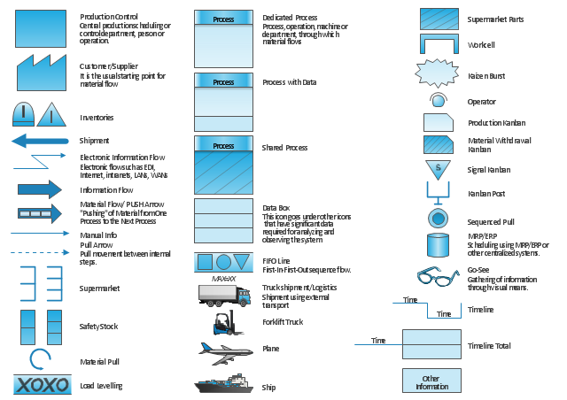
"Value stream mapping usually employs standard symbols to represent items and processes, therefore knowledge of these symbols is essential to correctly interpret the production system problems." [Value stream mapping. Wikipedia]
The vector stencils library Value stream mapping contains 43 symbols for drawing the value stream mapping diagrams using the ConceptDraw PRO diagramming and vector drawing software.
The example "Design elements - Value stream mapping diagram" is included in the Value Stream Mapping solution from the Quality area of ConceptDraw Solution Park.
VSM symbols
Flowchart Examples and Templates

Circuits and Logic Diagram Software

 Electrical Engineering
This solution extends ConceptDraw DIAGRAM.9.5 (or later) with electrical engineering samples, electrical schematic symbols, electrical diagram symbols, templates and libraries of design elements, to help you design electrical schematics, digital and analog
The vector stencils library "Lamps, acoustics, measuring instruments" contains 35 element symbols of lamps, acoustic components, electrical measuring instruments.
Use these shapes for drawing electrical schematics and electronic circuit diagrams in the ConceptDraw PRO diagramming and vector drawing software extended with the Electrical Engineering solution from the Engineering area of ConceptDraw Solution Park.
www.conceptdraw.com/ solution-park/ engineering-electrical
Ammeter

Frequency meter

Voltmeter

Galvanometer

Oscilloscope

Synchroscope

Thermometer

Wavemeter

Standard bell with 1 line input

Single-stroke bell with 1 line input

Siren with 1 line input

Standard bell with 2 lines input

Bell with 2 lines input

Bell with 1 line input

Single-stroke bell with 2 lines input

Siren with 2 lines input

Buzzer with 1 line input

Buzzer with 2 lines input

Buzzer with 2 lines input

Buzzer with 1 line input

Indicating lamp with 1 line input

Non-indicating lamp with 1 line input

Indicating lamp with 2 lines input

Non-indicating lamp with 2 lines input

Signal lamp

Lamp

Fluorescent lamp 2 terminal

Fluorescent lamp 4 terminal

Speaker

Speaker with microphone

Microphone

Capacitor microphone

Push-pull microphone

Microphone with 1 line

Microphone with 2 lines

 Security and Access Plans
The Security and Access Plans solution may be utilized in order to develop detailed equipment and cabling layout plans, blueprints, and wiring diagrams on internal and external security and access control systems, video surveillance and closed-circuit television (CCTV) systems. IT specialists, security managers, and other guards may use it to quickly design security plans and access plans, security chart, physical security plan, access chart, or access scheme on desire.
Network Glossary Definition


The logic gate diagram example "2-bit ALU" was redesigned from the Wikimedia Commons file: 2-bit ALU.svg.
[commons.wikimedia.org/ wiki/ File:2-bit_ ALU.svg]
This file is licensed under the Creative Commons Attribution-Share Alike 3.0 Unported license. [creativecommons.org/ licenses/ by-sa/ 3.0/ deed.en]
"In digital electronics, an arithmetic and logic unit (ALU) is a digital circuit that performs integer arithmetic and logical operations. The ALU is a fundamental building block of the central processing unit of a computer, and even the simplest microprocessors contain one for purposes such as maintaining timers. The processors found inside modern CPUs and graphics processing units (GPUs) accommodate very powerful and very complex ALUs; a single component may contain a number of ALUs. ...
Most of a processor's operations are performed by one or more ALUs. An ALU loads data from input registers. Then an external control unit tells the ALU what operation to perform on that data, and then the ALU stores its result into an output register. The control unit is responsible for moving the processed data between these registers, ALU and memory." [Arithmetic logic unit. Wikipedia]
The logic gate diagram example "2-bit ALU" was created using the ConceptDraw PRO diagramming and vector drawing software extended with the Electrical Engineering solution from the Engineering area of ConceptDraw Solution Park.
Logic gate diagram

- Electronic Components Symbols And Functions Pdf
- Design elements - Electrical circuits | Electrical Diagram Symbols ...
- Symbol Of The Elements Of Electronic Component Used In Circuit
- Electrical Diagram Symbols | Design elements - Semiconductor ...
- Electrical Schematic Symbols | Electrical Diagram Symbols | Wiring ...
- Electronic Schematic Symbols
- Electronic Symbols
- Electrical Diagram Symbols | Design elements - Semiconductors ...
- Electronic Component Symbols
- Design elements - Semiconductor diodes | Electrical Diagram ...
- Electrical Engineering | Electrical Engineering | How to Create an ...
- Electronic Symbol Switches
- Electrical Diagram Symbols
- Design elements - Electrical circuits | Electrical Engineering ...
- Electrical Diagram Symbols | Electrical Schematic Symbols | Design ...
- Design elements - Semiconductor diodes | Semiconductor diodes ...
- Electrical Drawing Software | Wiring Diagrams with ConceptDraw ...
- Electrical Diagram Symbols | Design elements - Lamps, acoustics ...
- Electronic Circuit Symbols
- Design elements - Electrical circuits | Design elements - Electrical ...