The vector stencils library "Pipes 1" contains 28 symbols of pipes. Use it for drawing plumbing and piping building plans, schematic diagrams, blueprints, or technical drawings of waste water disposal systems, hot and cold water supply systems in the ConceptDraw PRO diagramming and vector drawing software extended with the Plumbing and Piping Plans solution from the Building Plans area of ConceptDraw Solution Park.
General joint
Butt weld
Soldered / solvent
Screwed joint
Socket and spigot
Sleeve joint
Socket weld
Flanged / bolted

Swivel joint
Electrically bonded
Electrically insulated
End caps 1
End caps 2
End caps 3
Strainer

Separator
Exhaust silencer
Drain silencer
Open vent
Syphon drain
Hydrant
Tundish
Bell mouth
Exhaust head
Bursting disc
Flame arrester
Y strainer
Liquid seal open/closed
This PFD of jet fuel mercaptan oxidation treating was redrawn from Wikipedia file: ConvLPGMerox.png. [en.wikipedia.org/ wiki/ File:ConvKeroMerox.png]
This file is licensed under the Creative Commons Attribution-Share Alike 3.0 Unported icense. [creativecommons.org/ licenses/ by-sa/ 3.0/ deed.en]
"Merox is an acronym for mercaptan oxidation. It is a proprietary catalytic chemical process developed by UOP used in oil refineries and natural gas processing plants to remove mercaptans from LPG, propane, butanes, light naphthas, kerosene and jet fuel by converting them to liquid hydrocarbon disulfides.
The Merox process requires an alkaline environment which, in some of the process versions, is provided by an aqueous solution of sodium hydroxide (NaOH), a strong base, commonly referred to as caustic. In other versions of the process, the alkalinity is provided by ammonia, which is a weak base.
The catalyst in some versions of the process is a water-soluble liquid. In other versions, the catalyst is impregnated onto charcoal granules.
Processes within oil refineries or natural gas processing plants that remove mercaptans and/ or hydrogen sulfide (H2S) are commonly referred to as sweetening processes because they results in products which no longer have the sour, foul odors of mercaptans and hydrogen sulfide. The liquid hydrocarbon disulfides may remain in the sweetened products, they may be used as part of the refinery or natural gas processing plant fuel, or they may be processed further.
The Merox process is usually more economical than using a catalytic hydrodesulfurization process for much the same purpose." [en.wikipedia.org/ wiki/ Merox]
The process flow diagram (PFD) example "Jet fuel mercaptan oxidation treating" was drawn using the ConceptDraw PRO software extended with the Chemical and Process Engineering solution from the Chemical and Process Engineering area of ConceptDraw Solution Park.
Process flow diagram (PFD)
-jet-fuel-mercaptan-oxidation-treating---pfd.png--diagram-flowchart-example.png)
The vector stencils library "Valves and fittings" contains 104 symbols of valve components.
Use these icons for drawing industrial piping systems; process, vacuum, and fluids piping; hydraulics piping; air and gas piping; materials distribution; and liquid transfer systems in the ConceptDraw PRO software extended with the Chemical and Process Engineering solution from the Chemical and Process Engineering area of ConceptDraw Solution Park.
www.conceptdraw.com/ solution-park/ engineering-chemical-process
Electrically bonded

Bursting disc

Flame arrester

Strainer

Separator

Exhaust silencer

Bell mouth

Exhaust head

Hydrant

Drain silencer

Liquid seal open/closed

Y strainer

Gate valve

Globe valve

Globe valve 2

Globe valve 3

Screw-down valve

Lock-shield valve

Reel valve

Check valve

Check valve 2

Check valve 3

Screw-down check valve

Stop check valve

Diaphragm valve

Diaphragm valve 2

Diaphragm valve 3

Powered valve

Powered valve 2

Powered valve 3

Needle valve

Needle valve 2

Needle valve 3

Relief valve

Relief valve 2

Relief valve 3

Angle valve

Angle valve 2

Angle valve 3

Angle valve 4

Float operated valve

Float operated valve 2

Flanged valve

Butterfly valve

Butterfly valve 2

Wedge gate valve

Parallel slide valve

Ball valve

Ball valve 2

Ball valve 3

Relief angle valve vacuum

Relief angle valve pressure

Reducing valve

Reducing valve 2

Plug valve 3 way

Plug valve L point

Plug valve 2

Plug valve

Plug valve straight through

Plug valve T point

3-way plug valve

3-way plug valve 2

3-way plug valve 3

Mixing valve

Valve Manifold

Characterized port valve

Reducer

Reducer 2

General joint

Butt weld

Butt weld 2

Butt weld 3

Butt weld 4

Flanged/ bolted

Soldered / solvent

Soldered / solvent 2

Screwed joint

Screwed joint 2

Screwed joint 3

Socket and spigot

Socket and spigot 2

Socket and spigot 3

Sleeve

Sleeve 2

Screwed sleeve

Screwed sleeve 2

Socket weld

Socket weld 2

Swivel joint

Swivel joint 2

Swivel joint 3

End cap

End cap butt welded

End cap screwed

End cap socket and spigot

End cap fillet welded

End cap screwed and plugged

End cap quick release

End cap flanged and bolted

End cap flanged and bolted 2

Electrically insulated

Tundish

Syphon drain

Open vent

The vector stencils library "Valves and fittings" contains 104 symbols of valve components.
Use these icons for drawing industrial piping systems; process, vacuum, and fluids piping; hydraulics piping; air and gas piping; materials distribution; and liquid transfer systems in the ConceptDraw PRO software extended with the Chemical and Process Engineering solution from the Chemical and Process Engineering area of ConceptDraw Solution Park.
www.conceptdraw.com/ solution-park/ engineering-chemical-process
Use these icons for drawing industrial piping systems; process, vacuum, and fluids piping; hydraulics piping; air and gas piping; materials distribution; and liquid transfer systems in the ConceptDraw PRO software extended with the Chemical and Process Engineering solution from the Chemical and Process Engineering area of ConceptDraw Solution Park.
www.conceptdraw.com/ solution-park/ engineering-chemical-process
Electrically bonded
Bursting disc
Flame arrester
Strainer
Separator
Exhaust silencer
Bell mouth
Exhaust head
Hydrant
Drain silencer
Liquid seal open/closed
Y strainer
Gate valve
Globe valve
Globe valve 2
Globe valve 3
Screw-down valve
Lock-shield valve
Reel valve
Check valve
Check valve 2
Check valve 3
Screw-down check valve
Stop check valve
Diaphragm valve
Diaphragm valve 2
Diaphragm valve 3
Powered valve
Powered valve 2
Powered valve 3
Needle valve
Needle valve 2
Needle valve 3
Relief valve
Relief valve 2
Relief valve 3
Angle valve
Angle valve 2
Angle valve 3
Angle valve 4
Float operated valve
Float operated valve 2
Flanged valve
Butterfly valve
Butterfly valve 2
Wedge gate valve
Parallel slide valve
Ball valve
Ball valve 2
Ball valve 3
Relief angle valve vacuum
Relief angle valve pressure
Reducing valve
Reducing valve 2
Plug valve 3 way
Plug valve L point
Plug valve 2
Plug valve
Plug valve straight through
Plug valve T point
3-way plug valve
3-way plug valve 2
3-way plug valve 3
Mixing valve
Valve Manifold
Characterized port valve
Reducer
Reducer 2
General joint
Butt weld
Butt weld 2
Butt weld 3
Butt weld 4
Flanged/ bolted
Soldered / solvent
Soldered / solvent 2
Screwed joint
Screwed joint 2
Screwed joint 3
Socket and spigot
Socket and spigot 2
Socket and spigot 3
Sleeve
Sleeve 2
Screwed sleeve
Screwed sleeve 2
Socket weld
Socket weld 2
Swivel joint
Swivel joint 2
Swivel joint 3
End cap
End cap butt welded
End cap screwed
End cap socket and spigot
End cap fillet welded
End cap screwed and plugged
End cap quick release
End cap flanged and bolted
End cap flanged and bolted 2
Electrically insulated
Tundish
Syphon drain
Open vent
The vector stencils library "Pipes 1" contains 28 symbols of pipes. Use it for drawing plumbing and piping building plans, schematic diagrams, blueprints, or technical drawings of waste water disposal systems, hot and cold water supply systems in the ConceptDraw PRO diagramming and vector drawing software extended with the Plumbing and Piping Plans solution from the Building Plans area of ConceptDraw Solution Park.
General joint
Butt weld
Soldered / solvent
Screwed joint
Socket and spigot
Sleeve joint
Socket weld
Flanged / bolted
Swivel joint
Electrically bonded
Electrically insulated
End caps 1
End caps 2
End caps 3
Strainer
Separator
Exhaust silencer
Drain silencer
Open vent
Syphon drain
Hydrant
Tundish
Bell mouth
Exhaust head
Bursting disc
Flame arrester
Y strainer
Liquid seal open/closed
The vector stencils library "IGFET" contains 18 symbols of IGFET (insulated-gate field-effect transistor) elements for drawing electronic circuit diagrams.
"The metal–oxide–semiconductor field-effect transistor (MOSFET, MOS-FET, or MOS FET) is a transistor used for amplifying or switching electronic signals. Although the MOSFET is a four-terminal device with source (S), gate (G), drain (D), and body (B) terminals, the body (or substrate) of the MOSFET often is connected to the source terminal, making it a three-terminal device like other field-effect transistors. Because these two terminals are normally connected to each other (short-circuited) internally, only three terminals appear in electrical diagrams. The MOSFET is by far the most common transistor in both digital and analog circuits, though the bipolar junction transistor was at one time much more common. ...
An insulated-gate field-effect transistor or IGFET is a related term almost synonymous with MOSFET. The term may be more inclusive, since many "MOSFETs" use a gate that is not metal, and a gate insulator that is not oxide. Another synonym is MISFET for metal–insulator–semiconductor FET." [MOSFET
From Wikipedia]
The symbols example "Design elements - IGFET" was drawn using the ConceptDraw PRO diagramming and vector drawing software extended with the Electrical Engineering solution from the Engineering area of ConceptDraw Solution Park.
IGFET elements

The vector stencils library "Transistors" contains 30 symbols of transistors drawing electronic schematics and circuit diagrams.
"A transistor is a semiconductor device used to amplify and switch electronic signals and electrical power. It is composed of semiconductor material with at least three terminals for connection to an external circuit. A voltage or current applied to one pair of the transistor's terminals changes the current through another pair of terminals. Because the controlled (output) power can be higher than the controlling (input) power, a transistor can amplify a signal. Today, some transistors are packaged individually, but many more are found embedded in integrated circuits.
The transistor is the fundamental building block of modern electronic devices, and is ubiquitous in modern electronic systems. ...
Transistors are categorized by:
(1) Semiconductor material...: the metalloids germanium ... and silicon ... in amorphous, polycrystalline and monocrystalline form; the compounds gallium arsenide ... and silicon carbide ..., the alloy silicon-germanium ..., the allotrope of carbon graphene ...
(2) Structure: BJT, JFET, IGFET (MOSFET), insulated-gate bipolar transistor, "other types"
(3) Electrical polarity (positive and negative): n–p–n, p–n–p (BJTs); n-channel, p-channel (FETs)
(4) Maximum power rating: low, medium, high
(5) Maximum operating frequency: low, medium, high, radio (RF), microwave frequency...
(6) Application: switch, general purpose, audio, high voltage, super-beta, matched pair
(7) Physical packaging: through-hole metal, through-hole plastic, surface mount, ball grid array, power modules...
(8) Amplification factor..." [Transistor. Wikipedia]
The shapes example "Design elements - Transistors" was drawn using the ConceptDraw PRO diagramming and vector drawing software extended with the Electrical Engineering solution from the Engineering area of ConceptDraw Solution Park.
Transistor symbols

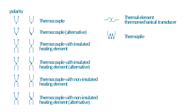
The vector stencils library "Thermo" contains 14 symbols of thermoelectric elements: thermal element, thermocouples with and without heating elements, thermoplile.
Use it for drawing electrical layouts, electronic schematics, and circuit diagrams.
"The thermoelectric effect is the direct conversion of temperature differences to electric voltage and vice versa. A thermoelectric device creates voltage when there is a different temperature on each side. Conversely, when a voltage is applied to it, it creates a temperature difference. At the atomic scale, an applied temperature gradient causes charge carriers in the material to diffuse from the hot side to the cold side.
This effect can be used to generate electricity, measure temperature or change the temperature of objects. Because the direction of heating and cooling is determined by the polarity of the applied voltage, thermoelectric devices can be used as temperature controllers.
The term "thermoelectric effect" encompasses three separately identified effects: the Seebeck effect, Peltier effect, and Thomson effect. Textbooks may refer to it as the Peltier–Seebeck effect. ...
Thermocouples and thermopiles are devices that use the Seebeck effect to measure the temperature difference between two objects, one connected to a voltmeter and the other to the probe. The temperature of the voltmeter, and hence that of the material being measured by the probe, can be measured separately using cold junction compensation techniques." [Thermoelectric effect. Wikipedia]
The shapes example "Design elements - Thermo" was drawn using the ConceptDraw PRO diagramming and vector drawing software extended with the Electrical Engineering solution from the Engineering area of ConceptDraw Solution Park.
Thermoelectric elements
- Power socket outlet layout | Pipes 1 - Vector stencils library | DVI ...
- Valves and fittings - Vector stencils library | Electrical Ball Fitting ...
- Electrically bonded
- Interior Design Piping Plan - Design Elements | Valves and fittings ...
- Engineering | Piping and Instrumentation Diagram Software ...
- Design elements - Valves and fittings | Valves and fittings - Vector ...
- Reducer
- Jet fuel mercaptan oxidation treating - PFD | Amine treating unit ...
- Valves and fittings - Vector stencils library
- Interior Design Piping Plan - Design Elements | Building Drawing ...
- Process Flowchart | Interior Design Piping Plan - Design Elements ...
- Lamps, acoustics, measuring instruments - Vector stencils library ...
- Interior Design Piping Plan - Design Elements | Design elements ...
- Building Drawing Design Element: Plumbing | Interior Design ...
- Interior Design Piping Plan - Design Elements | Design elements ...
- Pipes 1 - Vector stencils library
- Jet fuel mercaptan oxidation treating - PFD | Process flow diagram ...
- Elements location of a welding symbol | Welding symbols | Design ...
- Design elements - Pipes (part 2)
- Elements location of a welding symbol | Interior Design Piping Plan ...