Electrical Symbols — Power Sources

How To use House Electrical Plan Software


The vector stenvils library "Outlets" contains 57 symbols of electrical outlets for drawing building interior design, electrical floor plans and layouts of AC power plugs and sockets.
"AC power plugs and sockets are devices that allow electrically operated equipment to be connected to the primary alternating current (AC) power supply in a building. Electrical plugs and sockets differ in voltage and current rating, shape, size and type of connectors. The types used in each country are set by national standards, some of which are listed in the IEC technical report TR 60083, Plugs and socket-outlets for domestic and similar general use standardized in member countries of IEC.
Plugs and sockets for portable appliances started becoming available in the 1880s, to replace connections to light sockets with easier to use wall-mounted outlets. A proliferation of types developed to address the issues of convenience and protection from electric shock. Today there are approximately 20 types in common use around the world, and many obsolete socket types are still found in older buildings. Co-ordination of technical standards has allowed some types of plugs to be used over wide regions to facilitate trade in electrical appliances, and for the convenience of travellers and consumers of imported electrical goods. Some multi-standard sockets allow use of several different types of plugs; improvised or unapproved adapters between incompatible sockets and plugs may not provide the full safety and performance of an approved adapter." [AC power plugs and sockets. Wikipedia]
The example "Design elements - Outlets" was created using the ConceptDraw PRO diagramming and vector drawing software extended with the Electric and Telecom Plans solution from the Building plans area of ConceptDraw Solution Park.
Electrical outlet symbols

Electrical Symbols — Inductors

Electrical Symbols, Electrical Schematic Symbols

Electrical Symbols — Composite Assemblies

The vector stencils library "Electrical circuits" contains 49 element symbols of electrical and electronic devices, including ignitors, starters, transmitters, circuit protectors, transducers, radio and audio equipment.
Use it for drawing electronic circuit diagrams and electrical schematics.
"An electrical network is an interconnection of electrical elements such as resistors, inductors, capacitors, voltage sources, current sources and switches. An electrical circuit is a network consisting of a closed loop, giving a return path for the current. Linear electrical networks, a special type consisting only of sources (voltage or current), linear lumped elements (resistors, capacitors, inductors), and linear distributed elements (transmission lines), have the property that signals are linearly superimposable. They are thus more easily analyzed, using powerful frequency domain methods such as Laplace transforms, to determine DC response, AC response, and transient response.
A resistive circuit is a circuit containing only resistors and ideal current and voltage sources. Analysis of resistive circuits is less complicated than analysis of circuits containing capacitors and inductors. If the sources are constant (DC) sources, the result is a DC circuit.
A network that contains active electronic components is known as an electronic circuit. Such networks are generally nonlinear and require more complex design and analysis tools." [Electrical network. Wikipedia]
The symbils example "Design elements - Electrical circuits" was drawn using the ConceptDraw PRO diagramming and vector drawing software extended with the Electrical Engineering solution from the Engineering area of ConceptDraw Solution Park.
Electrical circuit elements

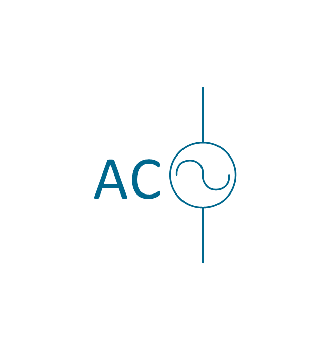
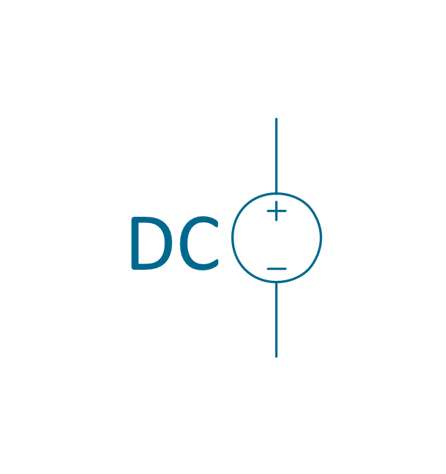
The vector stencils library "Power sources" contains 9 element symbols of power sources and batteries for drawing the electrical schematics and electronic circuit diagrams.
"A power supply is a device that supplies electric power to an electrical load. The term is most commonly applied to electric power converters that convert one form of electrical energy to another, though it may also refer to devices that convert another form of energy (mechanical, chemical, solar) to electrical energy. A regulated power supply is one that controls the output voltage or current to a specific value; the controlled value is held nearly constant despite variations in either load current or the voltage supplied by the power supply's energy source.
Every power supply must obtain the energy it supplies to its load, as well as any energy it consumes while performing that task, from an energy source. Depending on its design, a power supply may obtain energy from:
(1) Electrical energy transmission systems. Common examples of this include power supplies that convert AC line voltage to DC voltage.
(2) Energy storage devices such as batteries and fuel cells.
(3) Electromechanical systems such as generators and alternators.
(4) Solar power." [Power supply. Wikipedia]
The shapes example "Design elements - Power sources" was drawn using the ConceptDraw PRO diagramming and vector drawing software extended with the Electrical Engineering solution from the Engineering area of ConceptDraw Solution Park.
Power source symbols

The vector stencils library "Inductors" contains 41 symbols of inductor elements for drawing electronic circuit diagrams.
"An inductor, also called a coil or reactor, is a passive two-terminal electrical component which resists changes in electric current passing through it. It consists of a conductor such as a wire, usually wound into a coil. When a current flows through it, energy is stored temporarily in a magnetic field in the coil. When the current flowing through an inductor changes, the time-varying magnetic field induces a voltage in the conductor, according to Faraday’s law of electromagnetic induction, which opposes the change in current that created it.
An inductor is characterized by its inductance, the ratio of the voltage to the rate of change of current, which has units of henries (H). Inductors have values that typically range from 1 µH (10-6H) to 1 H. Many inductors have a magnetic core made of iron or ferrite inside the coil, which serves to increase the magnetic field and thus the inductance. Along with capacitors and resistors, inductors are one of the three passive linear circuit elements that make up electric circuits. Inductors are widely used in alternating current (AC) electronic equipment, particularly in radio equipment. They are used to block the flow of AC current while allowing DC to pass; inductors designed for this purpose are called chokes. They are also used in electronic filters to separate signals of different frequencies, and in combination with capacitors to make tuned circuits, used to tune radio and TV receivers." [Inductor. Wikipedia]
The symbols example "Design elements - Inductors" was drawn using the ConceptDraw PRO diagramming and vector drawing software extended with the Electrical Engineering solution from the Engineering area of ConceptDraw Solution Park.
Inductor elements

The vector stencils library "Transformers and windings" contains 29 element symbols of transformers, windings, couplers, metering devices, transductors, magnetic cores, chokes, and a variometer.
Use it to design the electromechanical device schematics and electronic circuit diagrams.
"A transformer is an electrical device that transfers energy between two circuits through electromagnetic induction. Transformers may be used in step-up or step-down voltage conversion, which 'transforms' an AC voltage from one voltage level on the input of the device to another level at the output terminals. This special function of transformers can provide control of specified requirements of current level as an alternating current source, or it may be used for impedance matching between mismatched electrical circuits to effect maximum power transfer between the circuits.
A transformer most commonly consists of two windings of wire that are wound around a common core to induce tight electromagnetic coupling between the windings. The core material is often a laminated iron core. The coil that receives the electrical input energy is referred to as the primary winding, while the output coil is called the secondary winding.
An alternating electric current flowing through the primary winding (coil) of a transformer generates an electromagnetic field in its surroundings and a varying magnetic flux in the core of the transformer. By electromagnetic induction this magnetic flux generates a varying electromotive force in the secondary winding, resulting in a voltage across the output terminals. If a load impedance is connected across the secondary winding, a current flows through the secondary winding drawing power from the primary winding and its power source." [Transformer. Wikipedia]
"An electromagnetic coil (or simply a "coil") is formed when a conductor is wound around a core or form to create an inductor or electromagnet. When electricity is passed through a coil, it generates a magnetic field. One loop of wire is usually referred to as a turn or a winding, and a coil consists of one or more turns. For use in an electronic circuit, electrical connection terminals called taps are often connected to a coil. Coils are often coated with varnish or wrapped with insulating tape to provide additional insulation and secure them in place. A completed coil assembly with one or more set of coils and taps is often called the windings.
Windings are used in transformers, electric motors, inductors, solenoids, loudspeakers, and many other applications." [Electromagnetic coil. Wikipedia]
The shapes example "Design elements - Transformers and windings" was drawn using the ConceptDraw PRO diagramming and vector drawing software extended with the Electrical Engineering solution from the Engineering area of ConceptDraw Solution Park.
Transformer and winding symbols

Network Glossary Definition


The vector stenvils library "Outlets" contains 57 symbols of electrical outlets.
Use these shapes for drawing building interior design, electrical floor plans and layouts of AC power plugs and sockets in the ConceptDraw PRO diagramming and vector drawing software.
The vector stencils library "Outlets" is included in the Electric and Telecom Plans solution from the Building Plans area of ConceptDraw Solution Park.
Single Outlet

Single Outlet and Switch

Emergency Circuit Single Outlet

Duplex Convenience Outlet

Emergency Circuit Duplex Outlet

Weatherproof Convenience Outlet

Range Outlet

Switch and Convenience Outlet

Radio and Convenience Outlet

Radio Outlet

Dedicated Duplex Outlet

Duplex Ground Fault Interrupter

Split Wired Duplex Outlet

240v Outlet

Floor Mounted Outlet

Floor Special-purpose Outlet

Heavy Duty Outlet

Heavy Duty Outlet with Convenience Outlet

Triplex Outlet

Split Wired Triplex Outlet

Quadruplex Outlet

Emergency Circuit Quadruplex Outlet

Special-purpose Outlet

Duplex Special-purpose Outlet

Special-purpose connection or provision for connection

Multi-outlet Assembly

Data/voice, Power Floor Mounted Outlet

Clock Hanger Outlet, Mounted

Blanked Outlet

Drop Outlet

Electrical Outlet

Fan Outlet

Junction Box

Lamp Holder

Lamp holder with pull switch

Pull Switch

Vapor discharge lamp outlet

Exit Light Outlet

Floor Receptacle

Telephone outlet

Floor Phone Outlet

Wall Phone Outlet

Weatherproof Phone Outlet

Phone Feed

Computer Data Outlet

Television outlet

Floor TV Outlet

TV Feed

Weatherproof TV Outlet

TV and Phone Outlet

Door Phone Outlet

Fax Outlet

Fiber Outlet

Multi-Purpose Outlet

Local Area Network Outlet

Wall Mounted Data Outlet

Wall Mounted Data/Telephone Outlet

Building Drawing Software for Design Site Plan


The vector stencils library "Terminals and connectors" contains 43 element symbols of terminals, connectors, plugs, polarized connectors, jacks, coaxial cables, and conductors.
Use it for drawing the wiring diagrams, electrical layouts, electronic schematics, and circuit diagrams in the ConceptDraw PRO diagramming and vector drawing software extended with the Electrical Engineering solution from the Engineering area of ConceptDraw Solution Park.
www.conceptdraw.com/ solution-park/ engineering-electrical
2-conductor jack

2-conductor plug

2-conductor jack 2

2-conductor plug 2

Normalled jacks

Normalled jack

Outside conductor coaxial

Center conductor coaxial

Large D connector

Small D connector

C header connector

Normalled jacks

Сontact, male

Сontact, female

Сontact, male 2

Сontact, female 2

Adapter, male - male

Adapter, male - male

Circuit terminal

Terminal board

Cable termination, complete

Cable termination, single-line

Cable termination, single-line 2

Shielded jack

Shielded plug

Coaxial jack

Coaxial plug

2-conductor, male

2-conductor, female

2-conductor, male 2

2-conductor, female 2

2-conductor, male 3

2-conductor, female 3

3-conductor, male

3-conductor, female

3-conductor, male 2

3-conductor, female 2

3-conductor, male 3

3-conductor, female 3

3-conductor, male 4

3-conductor, female 4

3-conductor, male 5

3-conductor, female 5

The vector stencils library "Power sources" contains 9 element symbols of power sources, power supplies and batteries.
Use these shapes for drawing the electrical schematics and electronic circuit diagrams in the ConceptDraw PRO diagramming and vector drawing software extended with the Electrical Engineering solution from the Engineering area of ConceptDraw Solution Park.
www.conceptdraw.com/ solution-park/ engineering-electrical
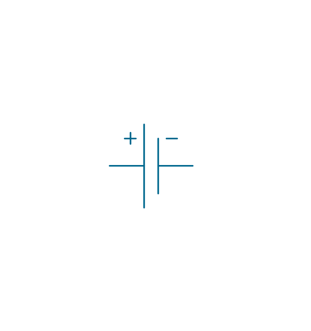
Battery with polarity labels
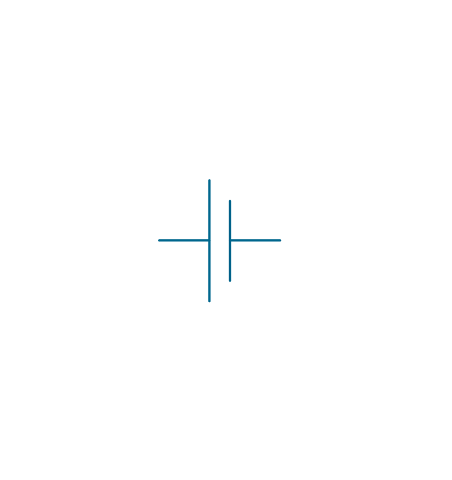
Battery
Ideal current source
Ideal voltage source
Oscillator

AC current source
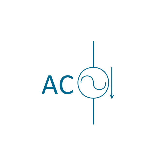
AC voltage source
DC current source
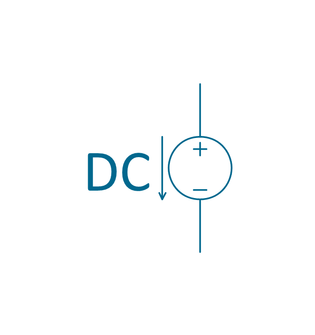
DC voltage source
- Ac Electric Symbol Architecture
- Electrical Plan Ac Symbol
- Ac Outlet Schematic Symbol
- How To use House Electrical Plan Software | Ac Control Panel Fan ...
- Electrical Symbols , Electrical Schematic Symbols | Block Digram Of Ac
- Electrical Symbols — Power Sources | Power sources - Vector ...
- Electrical Symbols — Inductors | Design elements - Inductors ...
- Electrical Outlet Symbol
- Home Electrical Plan | Electrical Symbols , Electrical Diagram ...
- How To use House Electrical Plan Software | Electrical Symbols ...
- Symbol Of Domestic Electrical Equipment
- Electrical Symbol Of An Cooker
- Electrical Drawing Software and Electrical Symbols | How To use ...
- Design elements - Electrical circuits | Design elements - Electrical ...
- Ac Outlets Socket Symbols
- Electrical Symbol Socket Switch Ac
- Electrical Symbol Vapor Discharge Lamp
- Cable TV - Vector stencils library | Electrical Symbols , Electrical ...
- Electrical Symbol Socket Outlet