Home Electrical Plan

Electrical Symbols, Electrical Diagram Symbols

How To use House Electrical Plan Software


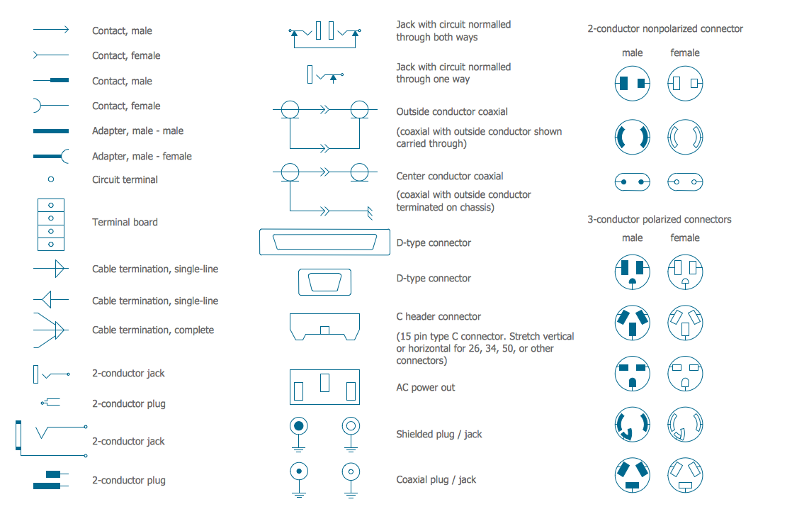
Electrical Symbols — Terminals and Connectors
 Network Layout Floor Plans
Network Layout Floor Plans solution extends ConceptDraw DIAGRAM software functionality with powerful tools for quick and efficient documentation the network equipment and displaying its location on the professionally designed Network Layout Floor Plans. Never before creation of Network Layout Floor Plans, Network Communication Plans, Network Topologies Plans and Network Topology Maps was not so easy, convenient and fast as with predesigned templates, samples, examples and comprehensive set of vector design elements included to the Network Layout Floor Plans solution. All listed types of plans will be a good support for the future correct cabling and installation of network equipment.
Swim Lane Flowchart Symbols

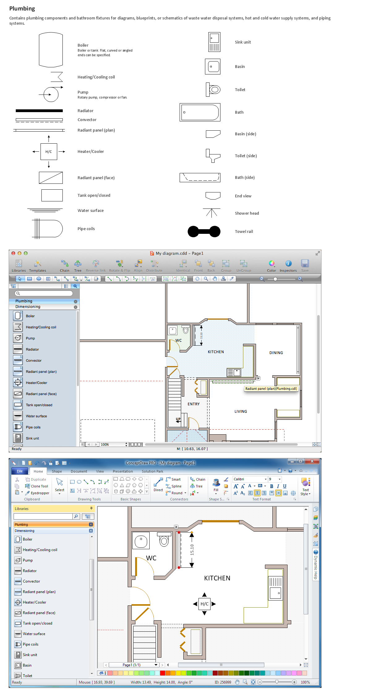
 Plumbing and Piping Plans
Plumbing and Piping Plans solution extends ConceptDraw DIAGRAM.2.2 software with samples, templates and libraries of pipes, plumbing, and valves design elements for developing of water and plumbing systems, and for drawing Plumbing plan, Piping plan, PVC Pipe plan, PVC Pipe furniture plan, Plumbing layout plan, Plumbing floor plan, Half pipe plans, Pipe bender plans.
Interior Design Registers, Drills and Diffusers - Design Elements

Building Drawing Software for Designing Plumbing

SysML

- Electrical Wiring Floor Plan Legend
- Floor Plan Plumbing Layout With Legend
- Cctv Legend Symbols
- Lighting Layout Legend
- Lighting Fixtures Plan Legends
- Legend Of Different Lights In Electrical Lighting Layout
- Ceiling Plan Lighting Legend
- How to Create a Reflected Ceiling Floor Plan | Lighting Legends For ...
- Reflected Ceiling Plan Lighting Symbols Legend
- Lighting and switch layout | Classroom lighting - Reflected ceiling ...