HelpDesk
How to Create a Fault Tree Analysis Diagram (FTD)

Interior Design. Site Plan — Design Elements
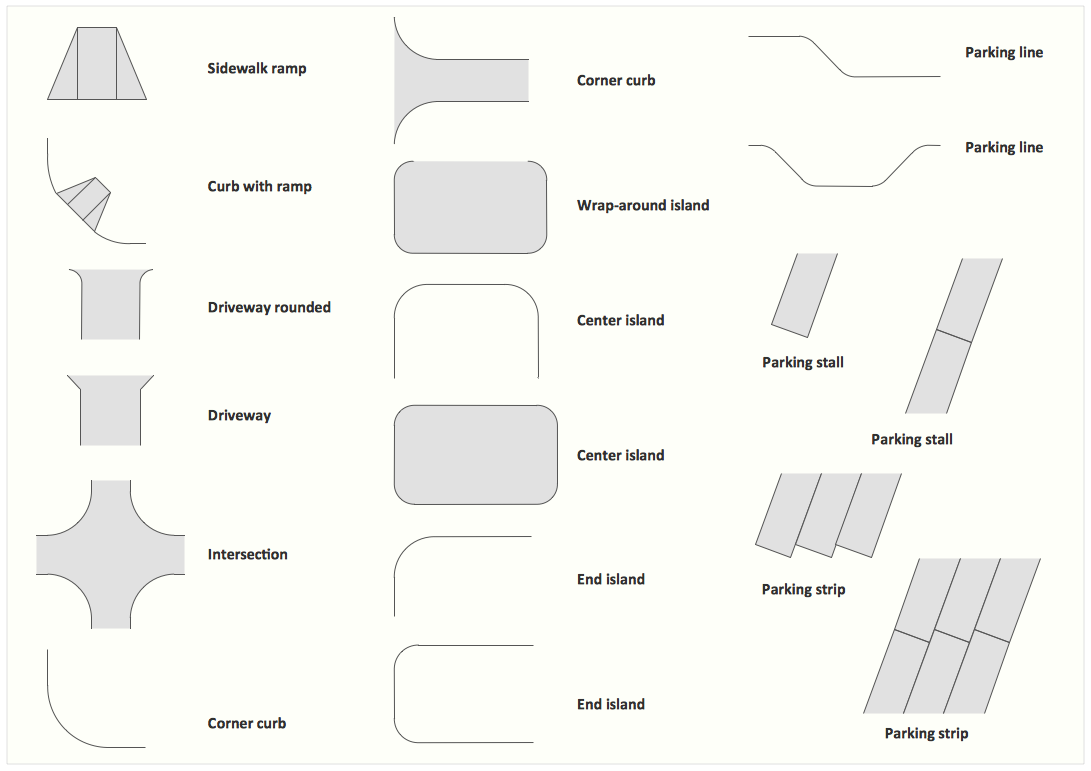
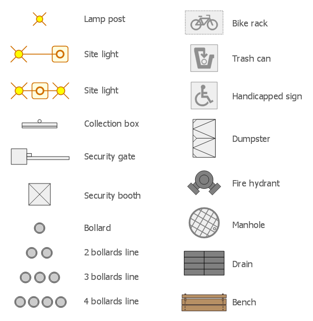
The vector stencils library "Site accessories" contains 18 symbols of vehicle access control equipment (tollbooth, tollgate, parking fees payment box), a handicapped sign, outdoor lighting, and garbage receptacles. Use it to design site plans, parking lots drawings and site management diagrams the ConceptDraw PRO diagramming and vector drawing software extended with the Site Plans solution from the Building Plans area of ConceptDraw Solution Park.
Lamp post

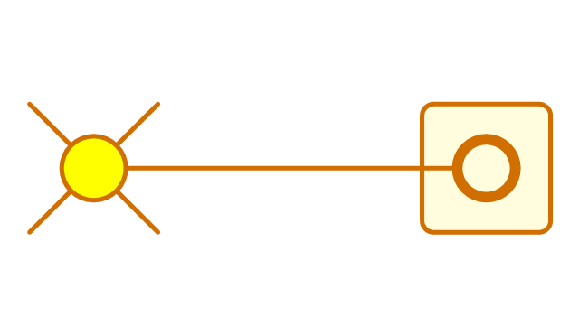
Site light 1
Site light 2
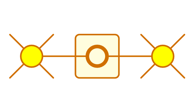
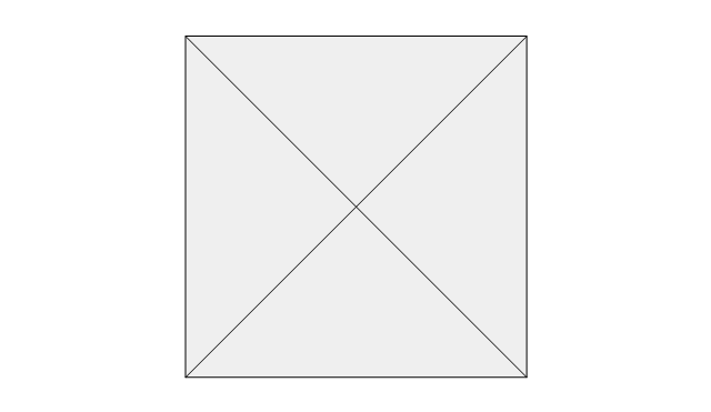
Collection box
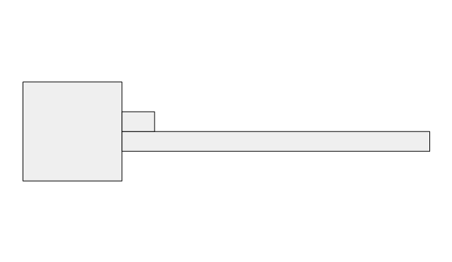
Security gate
Security booth
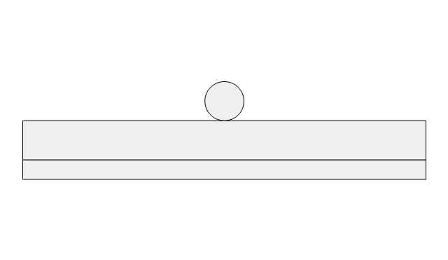
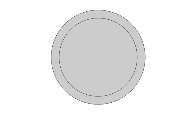
Bollard
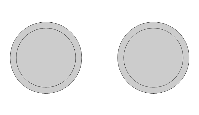
2 bollards line
3 bollards line
4 bollards line
Bike rack

Trash can
Handicapped sign
Dumpster
Fire hydrant
Manhole
Drain
Bench
The design elements library Site accessories contains 18 symbols of vehicle access control equipment (tollbooth, tollgate, parking fees payment box), a handicapped sign, outdoor lighting, and garbage receptacles.
"A site plan is an architectural plan, landscape architecture document, and a detailed engineering drawing of proposed improvements to a given lot. A site plan usually shows a building footprint, travelways, parking, drainage facilities, sanitary sewer lines, water lines, trails, lighting, and landscaping and garden elements." [Site plan. Wikipedia]
Use the Site accessories library to design plans, equipment layouts and maps of sites, parking lots, residential and commercial landscapes, parks, yards, plats, outdoor recreational facilities, and irrigation systems using ConceptDraw PRO diagramming and vector drawing software.
The design elements library Site accessories is contained in the Site Plans solution from the Building Plans area of ConceptDraw Solution Park.
ERD Symbols and Meanings


Building Drawing. Design Element Site Plan


 Engineering
This solution extends ConceptDraw DIAGRAM.4 with the ability to visualize industrial systems in electronics, electrical, chemical, process, and mechanical engineering.
 Sport Field Plans
Sport Field Plans solution extends ConceptDraw DIAGRAM with samples, templates and libraries of ready-made design elements for developing layouts of sport fields, recreation areas, playground layouts plans, and for professional drawing various sport field plans — for football, basketball, volleyball, golf, baseball, tennis, etc. Depict all your playground layout ideas easily and decisively implement the playground layout designs. Use the final colorful, strict and accurate ConceptDraw's playground layouts when designing the building documentation, brochures, booklets, advertising materials, sports editions, sport maps, business plans, on web sites of sport complexes, sport centers, hotels, etc.
- Gate Floor Plan Symbol
- Drawing Of Logic Gate Symbol
- Logic gate diagram - Vector stencils library | Symbol Of Nand Gate ...
- Sign Of Main Gate In Site Plan
- Manhole Symbol Show In Drawing
- Whats The Symbol For Gate On A Site Plan
- Design elements - Logic gate diagram
- Symbol Amplifier Diagram
- Access Control Symbols Gate Vehicle
- Security Gate
- Various Gates Symbol
- What Is The Sign Picture Of Gate In Architecture
- Site Plan Drawing Symbols Gate
- Symbol For A Gate In Landscape Design
- Site accessories - Vector stencils library | Site accessories - Vector ...
- Floor Plan Gate Symbol
- Gate Valve Symbol
- Electrical Drawing Software | Design elements - Site accessories ...
- Fire Hydrant Signs
- Draw The Electrical Or Gate