Electrical Symbols — Resistors

Electrical Symbols — Delay Elements

Electrical Symbols, Electrical Diagram Symbols

The vector stencils library "Resistors" contains 14 element symbols of resistors for drawing electronic schematics, circuit diagrams and electrical drawings.
"A resistor is a passive two-terminal electrical component that implements electrical resistance as a circuit element. Resistors act to reduce current flow, and, at the same time, act to lower voltage levels within circuits. Resistors may have fixed resistances or variable resistances, such as those found in thermistors, varistors, trimmers, photoresistors and potentiometers.
The current through a resistor is in direct proportion to the voltage across the resistor's terminals. This relationship is represented by Ohm's law ...
Resistors are common elements of electrical networks and electronic circuits and are ubiquitous in electronic equipment. Practical resistors can be composed of various compounds and films, as well as resistance wires (wire made of a high-resistivity alloy, such as nickel-chrome). Resistors are also implemented within integrated circuits, particularly analog devices, and can also be integrated into hybrid and printed circuits." [Resistor. Wikipedia]
The shapes example "Design elements - Resistors" was drawn using the ConceptDraw PRO diagramming and vector drawing software extended with the Electrical Engineering solution from the Engineering area of ConceptDraw Solution Park.
Resistor symbols

Electrical Symbols — Semiconductor

Electrical Symbols, Electrical Schematic Symbols

Electrical Symbols — Electrical Circuits

Electrical Symbols — Terminals and Connectors

The vector stencils library "Resistors" contains 14 element symbols of resistors.
Use these shapes for drawing electronic schematics, circuit diagrams and electrical drawings in the ConceptDraw PRO diagramming and vector drawing software extended with the Electrical Engineering solution from the Engineering area of ConceptDraw Solution Park.
www.conceptdraw.com/ solution-park/ engineering-electrical
Resistor
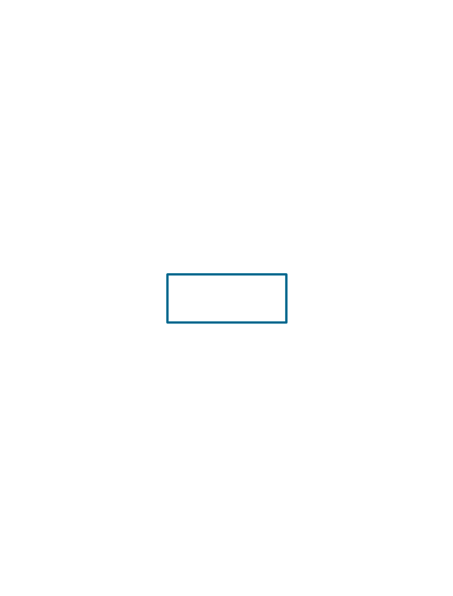
Resistor
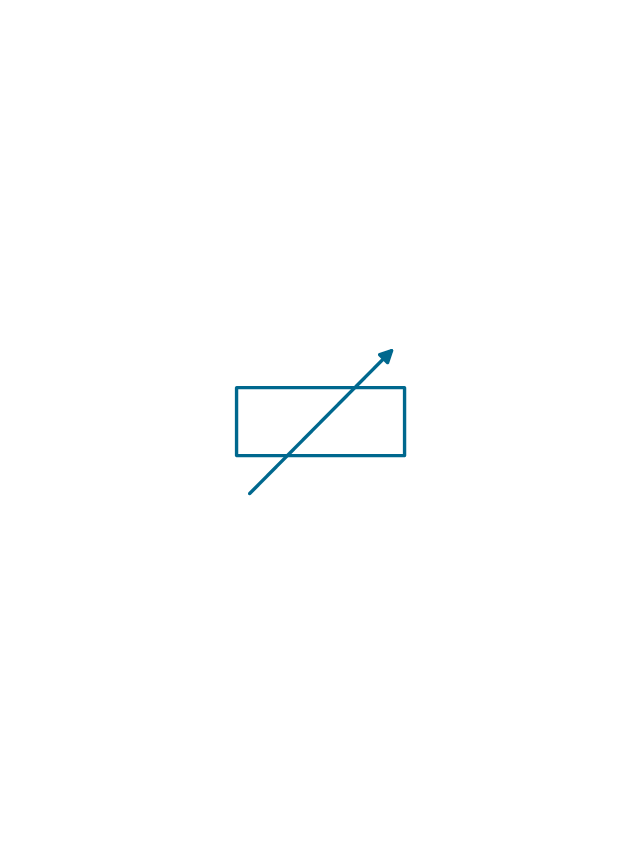
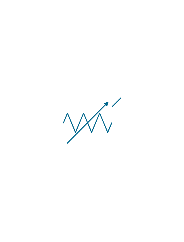
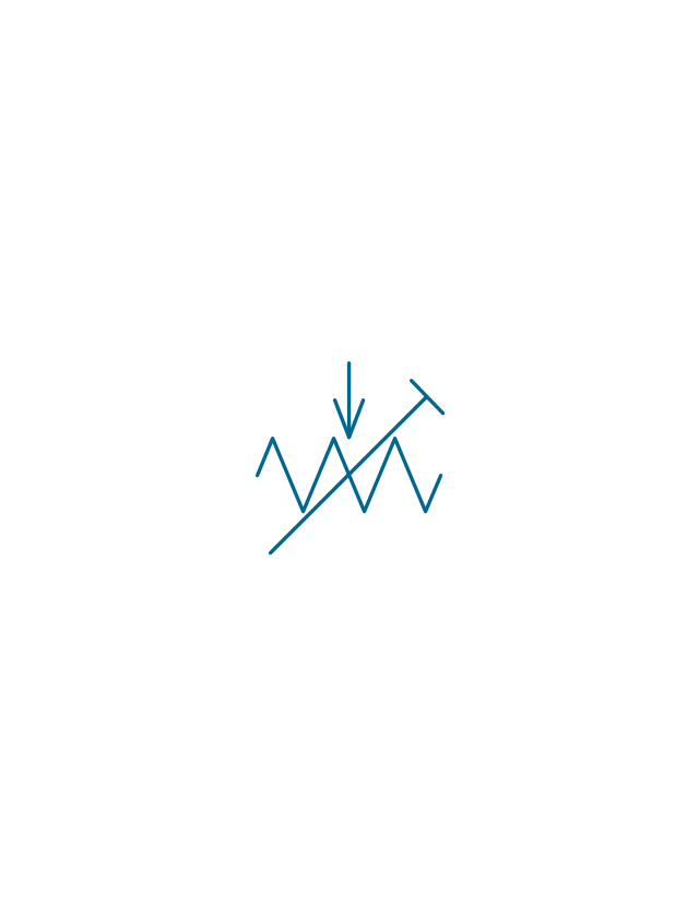
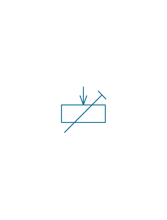
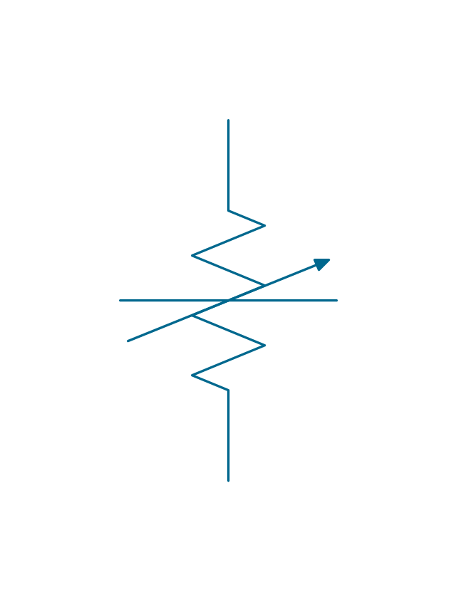
Variable resistor
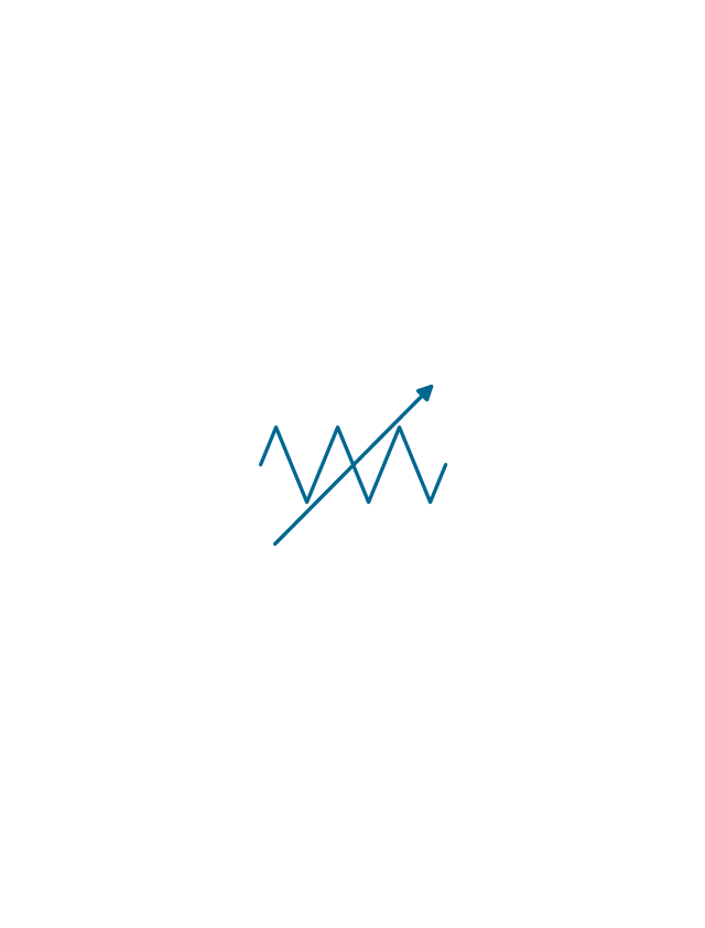
Variable resistor
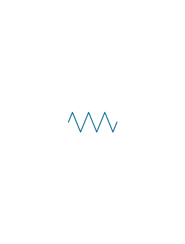
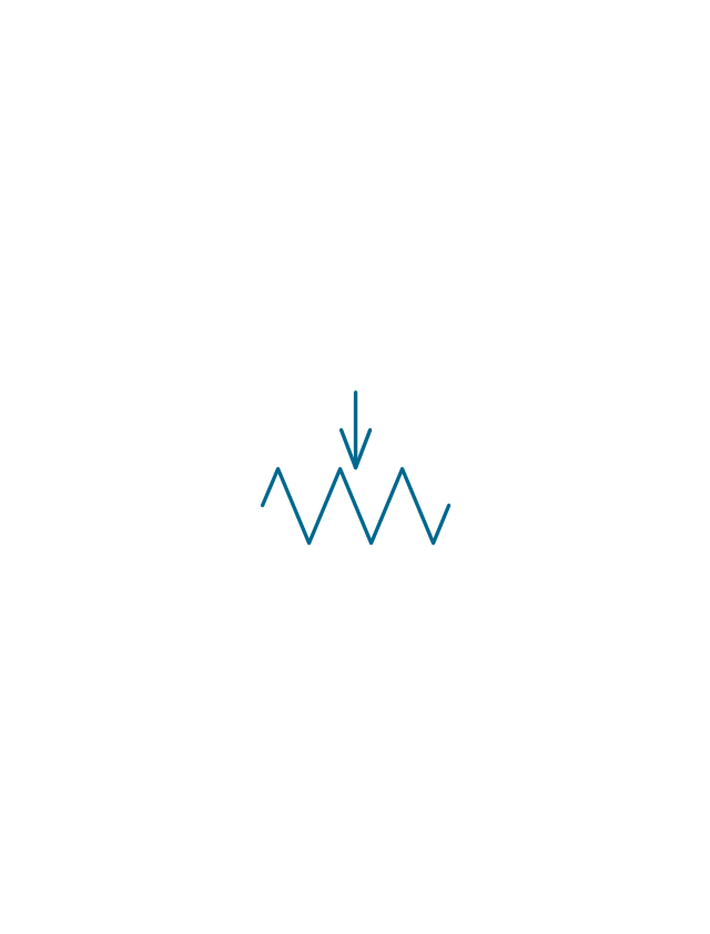
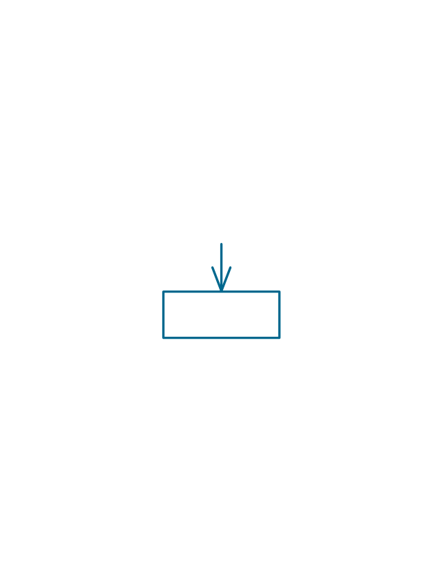
Continuous resistor
Continuous resistor
Pre-set resistor
Pre-set resistor
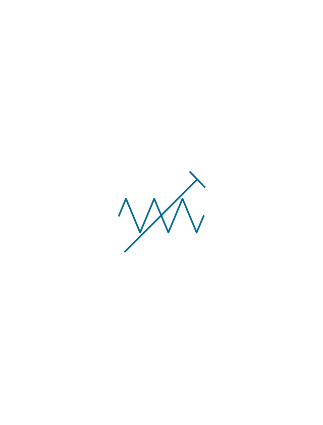
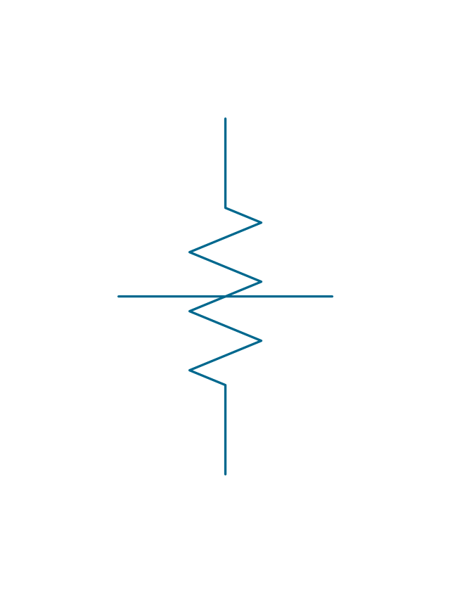
Potentiometer
Potentiometer
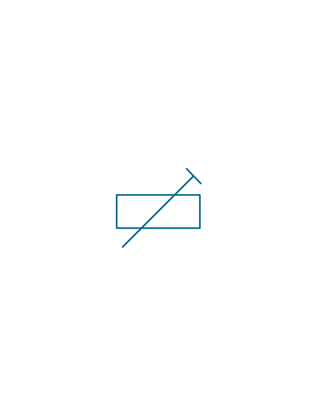
Pre-set potentiometer
Pre-set potentiometer
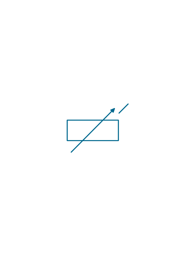
Variable attenuator
Attenuator
Electrical Symbols — IGFET

Wiring Diagrams with ConceptDraw DIAGRAM

The vector stencils library "Electrical circuits" contains 49 element symbols of electrical and electronic devices, including ignitors, starters, transmitters, circuit protectors, transducers, radio and audio equipment.
Use it for drawing electronic circuit diagrams and electrical schematics.
"An electrical network is an interconnection of electrical elements such as resistors, inductors, capacitors, voltage sources, current sources and switches. An electrical circuit is a network consisting of a closed loop, giving a return path for the current. Linear electrical networks, a special type consisting only of sources (voltage or current), linear lumped elements (resistors, capacitors, inductors), and linear distributed elements (transmission lines), have the property that signals are linearly superimposable. They are thus more easily analyzed, using powerful frequency domain methods such as Laplace transforms, to determine DC response, AC response, and transient response.
A resistive circuit is a circuit containing only resistors and ideal current and voltage sources. Analysis of resistive circuits is less complicated than analysis of circuits containing capacitors and inductors. If the sources are constant (DC) sources, the result is a DC circuit.
A network that contains active electronic components is known as an electronic circuit. Such networks are generally nonlinear and require more complex design and analysis tools." [Electrical network. Wikipedia]
The symbils example "Design elements - Electrical circuits" was drawn using the ConceptDraw PRO diagramming and vector drawing software extended with the Electrical Engineering solution from the Engineering area of ConceptDraw Solution Park.
Electrical circuit elements

- Draw Symbols Of Following Variable Resistor
- Resistors - Vector stencils library | Design elements - Resistors ...
- Electrical Symbols , Electrical Diagram Symbols | Electrical Symbols ...
- Design elements - Resistors | Design elements - Electrical circuits ...
- Design elements - Resistors | Varistor Variable Resistor Symbol
- Electrical Symbols , Electrical Diagram Symbols | Electrical Drawing ...
- Electrical Resistors Shapes
- Electrical Symbols — Thermo | Electrical Symbols — Switches and ...
- Electrical Drawing Software and Electrical Symbols | Electrical ...
- Electrical Symbols , Electrical Diagram Symbols | Electrical Symbols ...
- Electrical Symbols — Resistors | Design elements - Resistors ...
- Design elements - Electrical circuits | Electrical Symbols , Electrical ...
- Electrical Symbols — Resistors | Electrical Diagram Software ...
- Electrical Symbols — Resistors | Electrical Symbols , Electrical ...
- Electrical Symbol For Resistor Black And White
- Electrical Drawing Software and Electrical Symbols | Wiring ...
- Electrical Symbols , Electrical Diagram Symbols | How To use House ...
- Design elements - Resistors | Electrical Symbols — Resistors | How ...
- Electrical Symbols , Electrical Diagram Symbols | Electrical Symbols ...
- Design elements - Resistors | Design elements - Electrical circuits ...