Physics Diagrams
HelpDesk
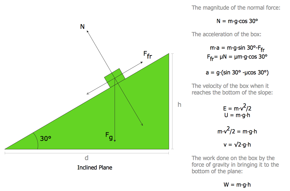
How to Draw Physics Diagrams

 Physics
Physics solution extends ConceptDraw DIAGRAM software with templates, samples and libraries of vector stencils for drawing the physical illustrations, diagrams and charts.
Stakeholder Mapping Tool

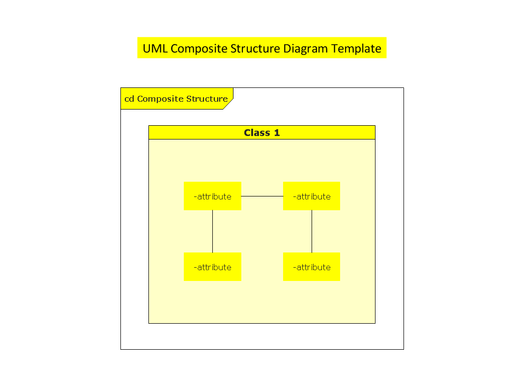
UML Composite Structure Diagram

Components of ER Diagram

 Stakeholder Onion Diagrams
The Stakeholder Onion Diagram is often used as a way to view the relationships of stakeholders to a project goal. A basic Onion Diagram contains a rich information. It shows significance of stakeholders that will have has influence to the success achieve
 AWS Architecture Diagrams
AWS Architecture Diagrams with powerful drawing tools and numerous predesigned Amazon icons and AWS simple icons is the best for creation the AWS Architecture Diagrams, describing the use of Amazon Web Services or Amazon Cloud Services, their application for development and implementation the systems running on the AWS infrastructure. The multifarious samples give you the good understanding of AWS platform, its structure, services, resources and features, wide opportunities, advantages and benefits from their use; solution’s templates are essential and helpful when designing, description and implementing the AWS infrastructure-based systems. Use them in technical documentation, advertising and marketing materials, in specifications, presentation slides, whitepapers, datasheets, posters, etc.
 IDEF Business Process Diagrams
Use the IDEF Business Process Diagrams solution to create effective database designs and object-oriented designs, following the integration definition methodology.
Electrical Symbols — MOSFET

- Free Body Diagram Drawing Software
- Online Free Body Diagram Creator
- Free - body diagram | How to Draw Physics Diagrams in ...
- Physics Diagrams | How to Draw Physics Diagrams in ConceptDraw ...
- Free Body Diagram Of Mos In Wikipedia
- Tool For Drawing Free Body Diagram
- How To Make Free Body Diagrams On A Computer
- Free Body Diagram Mos
- Force Diagram Creator