Electrical Symbols, Electrical Diagram Symbols

The vector stencils library "Lamps, acoustics, measuring instruments" contains 35 element symbols of lamps, acoustic components, electrical measuring instruments.
Use these shapes for drawing electrical schematics and electronic circuit diagrams in the ConceptDraw PRO diagramming and vector drawing software extended with the Electrical Engineering solution from the Engineering area of ConceptDraw Solution Park.
www.conceptdraw.com/ solution-park/ engineering-electrical
Ammeter

Frequency meter

Voltmeter

Galvanometer

Oscilloscope

Synchroscope

Thermometer

Wavemeter

Standard bell with 1 line input

Single-stroke bell with 1 line input

Siren with 1 line input

Standard bell with 2 lines input

Bell with 2 lines input

Bell with 1 line input

Single-stroke bell with 2 lines input

Siren with 2 lines input

Buzzer with 1 line input

Buzzer with 2 lines input

Buzzer with 2 lines input

Buzzer with 1 line input

Indicating lamp with 1 line input

Non-indicating lamp with 1 line input

Indicating lamp with 2 lines input

Non-indicating lamp with 2 lines input

Signal lamp

Lamp

Fluorescent lamp 2 terminal

Fluorescent lamp 4 terminal

Speaker

Speaker with microphone

Microphone

Capacitor microphone

Push-pull microphone

Microphone with 1 line

Microphone with 2 lines

Electrical Symbols — Switches and Relays

Mechanical Drawing Symbols

Electrical Symbols — Analog and Digital Logic

Electrical Symbols — Composite Assemblies

 Electrical Engineering
This solution extends ConceptDraw DIAGRAM.9.5 (or later) with electrical engineering samples, electrical schematic symbols, electrical diagram symbols, templates and libraries of design elements, to help you design electrical schematics, digital and analog
Electrical Symbols — Transmission Paths
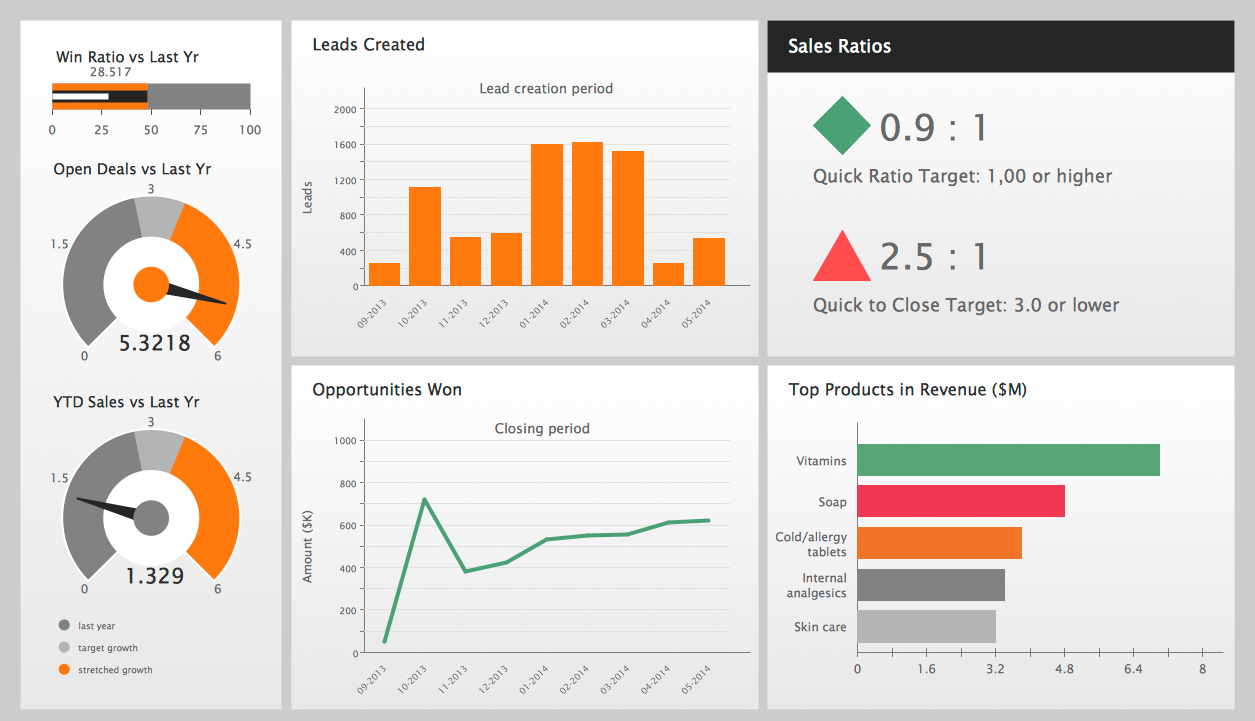
Performance Indicators
 Line Graphs
How to draw a Line Graph with ease? The Line Graphs solution extends the capabilities of ConceptDraw DIAGRAM with professionally designed templates, samples, and a library of vector stencils for drawing perfect Line Graphs.
- Project Completion Indicator
- Symbols Of Various Temperature Sensors Indicators And Transmitters
- Network Drawing Software | Labelled Diagram Of Electric Circuit
- Instruments - Vector stencils library | Steam Turbine Circuit Diagram ...
- Composition indicators - Vector stencils library | Design elements ...
- Electrical Symbols — Thermo | Electrical Symbols — Resistors ...
- Design elements - Composition charts and indicators | How To Draw ...
- Draw The Symbol Of Galvanometer
- Design elements - Instruments | Instruments - Vector stencils library ...
- How to Convert MS Visio® 2003-2010 File to ConceptDraw PRO ...