Network Gateway Router


 Computer Network Diagrams
Computer Network Diagrams solution extends ConceptDraw PRO software with samples, templates and libraries of vector stencils for drawing the computer network topology diagrams.
Network Diagramming with ConceptDraw PRO

"Physical topology refers to the placement of the network's various components, including device location and cable installation...
The shape of the cabling layout used to link devices is called the physical topology of the network. This refers to the layout of cabling, the locations of nodes, and the interconnections between the nodes and the cabling. The physical topology of a network is determined by the capabilities of the network access devices and media, the level of control or fault tolerance desired, and the cost associated with cabling or telecommunications circuits." [Network topology. Wikipedia]
This physical LAN diagram example was created using the ConceptDraw PRO diagramming and vector drawing software extended with the Computer and Networks solution from the Computer and Networks area of ConceptDraw Solution Park.
LAN physical topology

Used Solutions
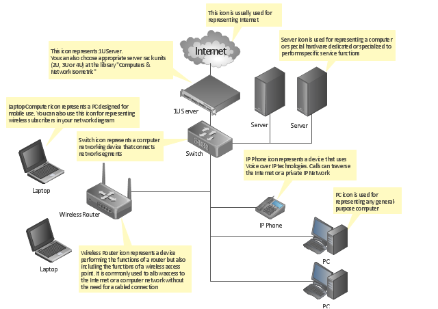
"A computer network diagram is a schematic depicting the nodes and connections amongst nodes in a computer network or, more generally, any telecommunications network. ...
Readily identifiable icons are used to depict common network appliances e.g. Router, and the style of lines between them indicate the type of connection. Clouds are used to represent networks external to the one pictured for the purposes of depicting connections between internal and external devices, without indicating the specifics of the outside network. ...
At different scales diagrams may represent various levels of network granularity. At the LAN level, individual nodes may represent individual physical devices, such as hubs or file servers, while at the WAN level, individual nodes may represent entire cities. In addition, when the scope of a diagram crosses the common LAN/ MAN/ WAN boundaries, representative hypothetical devices may be depicted instead of showing all actually existing nodes." [Computer network diagram. Wikipedia]
The computer network diagram template for the ConceptDraw PRO diagramming and vector drawing software is included in the Computer and Networks solution from the Computer and Networks area of ConceptDraw Solution Park.
Computer network diagram template
"In electronics, a vacuum tube, electron tube (in North America), tube, or thermionic valve or valve (in British English) is a device controlling electric current through a vacuum in a sealed container. The simplest vacuum tube, the diode, contains only two elements; current can only flow in one direction through the device between the two electrodes, as electrons emitted by the hot cathode travel through the tube and are collected by the anode. Addition of a third and additional electrodes allows the current flowing between cathode and anode to be controlled in various ways. The device can be used as an electronic amplifier, a rectifier, an electronically controlled switch, an oscillator, and for other purposes.
Vacuum tubes mostly rely on thermionic emission of electrons from a hot filament or a cathode heated by the filament. Some electron tube devices rely on the properties of a discharge through an ionized gas." [Vacuum tube. Wikipedia]
"The EL34 is a thermionic valve or vacuum tube of the power pentode type. It has an international octal base (indicated by the '3' in the part number) and is found mainly in the final output stages of audio amplification circuits and was designed to be suitable as a series regulator by virtue of its high permissible voltage between heater and cathode and other parameters. The American RETMA tube designation number for this tube is 6CA7. Russian analog is 6P27S (Cyrillic: 6П27C )" [EL34. Wikipedia]
This circuit diagram sample was redrawn from the Wikipedia Commons file: EL34 schematics (circuit diagram).gif. [commons.wikimedia.org/ wiki/ File:EL34_ schematics_ %28circuit_ diagram%29.gif]
The example "Circuit diagram - EL 34 schematics" was drawn using the ConceptDraw PRO diagramming and vector drawing software extended with the Electrical Engineering solution from the Engineering area of ConceptDraw Solution Park.
EL34 shemathics

- Physical LAN and WAN diagram - Template | Network Diagram ...
- Network Topologies | Fully Connected Network Topology Diagram ...
- Diagram Physical Topologies | Logical network topology diagram ...
- Home area networks (HAN). Computer and Network Examples ...
- Network Diagram Software Physical Network Diagram | Network ...
- Electronic Devices Icon Diagram
- Audio Visual Diagram Drawing Software
- How to Create a Hook Up Diagram | Making Your Audio and Video ...
- Identify And Draw Audio Visual Devices
- Audio and Video Connectors | How to Create a Hook Up Diagram ...
- How to Create a Hook Up Diagram
- How to Create a Hook Up Diagram | Audio & Video Connections ...
- Wide area network (WAN) topology. Computer and Network Examples
- Diagrams Showing Various Network Topologies
- Audio Visual Cables and Connectors | How to Create a Hook Up ...
- Cisco Network Templates | Logical network diagram - Template ...
- Wireless Networks | How to Create a Wireless Network Diagram ...
- How to Create a Hook Up Diagram | ConceptDraw Arrows10 ...
- Star Network Topology | How To use Switches in Network Diagram ...
- Various Network Topologies