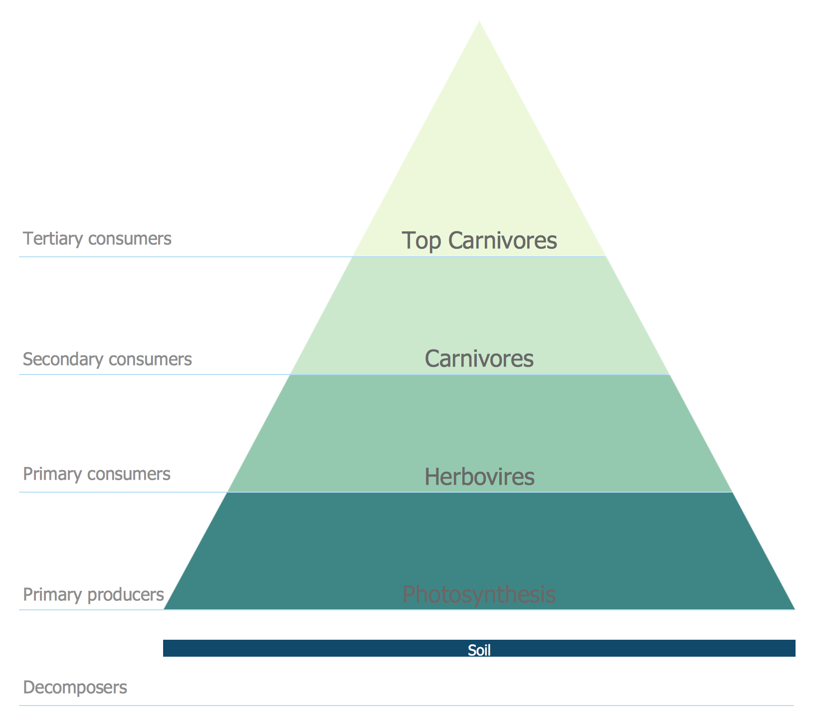
Energy Pyramid Diagram
Electrical Symbols — Semiconductor

Electrical Symbols — Power Sources

Electrical Symbols — Rotating Equipment

Electrical Symbols, Electrical Diagram Symbols

"Waste minimization is the process and the policy of reducing the amount of waste produced by a person or a society.
Waste minimization involves efforts to minimize resource and energy use during manufacture. For the same commercial output, usually the fewer materials are used, the less waste is produced. Waste minimization usually requires knowledge of the production process, cradle-to-grave analysis (the tracking of materials from their extraction to their return to earth) and detailed knowledge of the composition of the waste. ...
In the waste hierarchy, the most effective approaches to managing waste are at the top. In contrast to waste minimisation, waste management focuses on processing waste after it is created, concentrating on re-use, recycling, and waste-to-energy conversion." [Waste minimisation. Wikipedia]
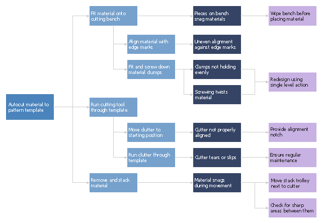
The process decision program chart (PDPC) example "Minimization of material wastage" was created using the ConceptDraw PRO diagramming and vector drawing software extended with the solution "Seven Management and Planning Tools" from the Management area of ConceptDraw Solution Park.
Waste minimization involves efforts to minimize resource and energy use during manufacture. For the same commercial output, usually the fewer materials are used, the less waste is produced. Waste minimization usually requires knowledge of the production process, cradle-to-grave analysis (the tracking of materials from their extraction to their return to earth) and detailed knowledge of the composition of the waste. ...
In the waste hierarchy, the most effective approaches to managing waste are at the top. In contrast to waste minimisation, waste management focuses on processing waste after it is created, concentrating on re-use, recycling, and waste-to-energy conversion." [Waste minimisation. Wikipedia]
The process decision program chart (PDPC) example "Minimization of material wastage" was created using the ConceptDraw PRO diagramming and vector drawing software extended with the solution "Seven Management and Planning Tools" from the Management area of ConceptDraw Solution Park.
PDPC
"The proton–proton chain reaction is one of several fusion reactions by which stars convert hydrogen to helium, the primary alternative being the CNO cycle. The proton–proton chain dominates in stars the size of the Sun or smaller.
In general, proton–proton fusion can occur only if the temperature (i.e. kinetic energy) of the protons is high enough to overcome their mutual electrostatic or Coulomb repulsion.
In the Sun, deuterium-producing events are so rare (diprotons, the much more common result of nuclear reactions within the star, immediately decay back into two protons) that a complete conversion of the star's hydrogen would take more than 1010 (ten billion) years at the prevailing conditions of its core. The fact that the Sun is still shining is due to the slow nature of this reaction; if it went more quickly, the Sun would have exhausted its hydrogen long ago." [Proton–proton chain reaction. Wikipedia]
The nuclear reaction diagram example "Proton-proton chain reaction" was created using the ConceptDraw PRO diagramming and vector drawing software extended with the Physics solution from the Science and Education area of ConceptDraw Solution Park.
Proton-proton chain reaction diagram

Electrical Drawing Software and Electrical Symbols

Chemical Engineering

Electrical Symbols — Transformers and Windings
- How To Draw Energy Conversion Diagram
- Example Of Energy Transformation Clipart
- Energy Pyramid Diagram | Energy resources diagram | | Energy
- Proton-proton chain reaction diagram | Draw The Following ...
- Process decision program chart (PDPC) - Personal activity | Process ...
- Fuel Conversation Drawing Chart
- Fishbone Diagram | Factory layout floor plan | Manufacturing and ...
- Preventive Action Chart
- PDPC | Process decision program chart (PDPC) - Personal activity ...
- Dc Dc Converter Symbol