Cisco Network Topology. Cisco icons, shapes, stencils and symbols
Cisco Products Additional. Cisco icons, shapes, stencils and symbols
")
This example of cloud computing system architecture diagram was redesigned from the Wikimedia Commons file: ArchitectureCloudLinksSameSite.png. [commons.wikimedia.org/ wiki/ File:ArchitectureCloudLinksSameSite.png]
"An example showing a grid computing system connecting many personal computers over the Internet using inter-process network communication ...
In computer science, inter-process communication (IPC) is the activity of sharing data across multiple and commonly specialized processes using communication protocols. Typically, applications using IPC are categorized as clients and servers, where the client requests data and the server responds to client requests." [en.wikipedia.org/ wiki/ Inter-process_ communication]
"Grid computing is the collection of computer resources from multiple locations to reach a common goal. The grid can be thought of as a distributed system with non-interactive workloads that involve a large number of files. Grid computing is distinguished from conventional high performance computing systems such as cluster computing in that grid computers have each node set to perform a different task/ application. Grid computers also tend to be more heterogeneous and geographically dispersed (thus not physically coupled) than cluster computers." [Grid computing. Wikipedia]
The diagram example "Grid computing system architecture" was created using ConceptDraw PRO diagramming and vector drawing software extended with the Azure Architecture solution from the Computer and Networks area of ConceptDraw Solution Park.
Grid computing system architecture diagram
 Network Security Diagrams
The Network Security Diagrams solution enhances the ConceptDraw PRO v10 functionality with large collection of predesigned vector stencils of cybersecurity clipart, shapes, icons and connectors to help you succeed in designing professional and accurate Ne
Cisco Routers. Cisco icons, shapes, stencils and symbols
 Router subdued Router-with-silicon-switch Wavelength-router NetFlow-router uBR910 Broadband-router Gigabit-switch-ATM-tag-router ATM-tag-switch-router Edge-label-switch-router Edge-label-switch-router-with-NetFlow Cisco-7505 Cisco-7507 Cisco-7500-ARS-(7513) Voice-enabled-router TDM-router IP-telephony-router IAD-router Content-service-router Cisco-storage-router Router-with-firewall Wireless-router ASR-1000-series ATM-3800 AXP Cable-modem Ground-terminal. Network equipment refers to hardware devices designed for local area networks, both wired and wireless. Active network equipment is powered from the electricity supply, portable battery, the computer via USB-port and other sources, also it can be used for amplification, conversion and processing of the network signal.")
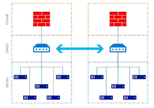
The vector stencils library "Cisco network topology" contains 89 symbols of Cisco network devices and design elements for drawing computer network topology diagrams.
"There are two basic categories of network topologies:
(1) Physical topologies,
(2) Logical topologies.
The shape of the cabling layout used to link devices is called the physical topology of the network. This refers to the layout of cabling, the locations of nodes, and the interconnections between the nodes and the cabling. The physical topology of a network is determined by the capabilities of the network access devices and media, the level of control or fault tolerance desired, and the cost associated with cabling or telecommunications circuits.
The logical topology in contrast, is the way that the signals act on the network media, or the way that the data passes through the network from one device to the next without regard to the physical interconnection of the devices." [Network topology. Wikipedia]
The symbols example "Cisco network topology - Vector stencils library" was created using the ConceptDraw PRO diagramming and vector drawing software extended with the Cisco Network Diagrams solution from the Computer and Networks area of ConceptDraw Solution Park.
www.conceptdraw.com/ solution-park/ computer-networks-cisco
Router

Broadband router

Router firewall

Wireless router

Workgroup switch

ATM switch

ISDN switch

Multilayer switch

Protocol translator

Communications server

Transpath

Bridge

Terminal server

Route switch processor

Content engine (cache director)
-cisco-network-topology---vector-stencils-library.png--diagram-flowchart-example.png)
Management engine (ME 1100)
-cisco-network-topology---vector-stencils-library.png--diagram-flowchart-example.png)
Switch processor

ITP

Voice gateway

BBSM

ATA

SIP Proxy server

NetRanger

Cisco 1000

IP

System controller

ACE

Directory server

ADM

Cisco Unity Express

Unity server

Cisco security

CallManager

DSLAM

H.323

CDM (Content Distribution Manager)
-cisco-network-topology---vector-stencils-library.png--diagram-flowchart-example.png)
ICM

Access point

Wireless bridge

Wireless connectivity

Guard

Mobile access router

Carrier Routing System (CRS)
-cisco-network-topology---vector-stencils-library.png--diagram-flowchart-example.png)
Vault

Workstation

PC

Macintosh

Cloud, gold

Cloud, white

Cloud, standard color

Cisco security management

PBX

DPT

Government building

Headquarters, blue

Router in building

Man

Woman

Workgroup switch, subdued

Router, subdued

File server

Firewall, horizontal

Firewall, vertical

Firewall, vertical, subdued

Lock

Key

Lock and key

Car

Truck

File cabinet

Breakout box

Breakout box, blue

Host

Relational database

Modem

BBS (Bulletin Board System)
-cisco-network-topology---vector-stencils-library.png--diagram-flowchart-example.png)
Satellite

Satellite dish

UPS

RPS

MAU

PAD

PAD X.28

Diskette

Contact center

Page icon
Antenna

Antenna, blue

Radio tower

The vector stencils library "Cisco products additional" contains 141 symbols of computer network devices and equipment for drawing Cisco network diagrams.
The symbols example "Cisco products additional - Vector stencils library" was created using the ConceptDraw PRO diagramming and vector drawing software extended with the Cisco Network Diagrams solution from the Computer and Networks area of ConceptDraw Solution Park.
www.conceptdraw.com/ solution-park/ computer-networks-cisco
Protocol translator
CiscoWorks workstation
Access server
Workgroup director
Network management appliance
Storage Solution Engine (SSE)
-cisco-products-additional---vector-stencils-library.png--diagram-flowchart-example.png)
Software based router on file / application server
Cisco MeetingPlace Express
PC router card
Transpath
Bridge
IOS SLB
100BaseT hub
uBR910
CDDI-FDDI
PC adapter card
VIP
CSM-S
Terminal server
Route/Switch processor with Si
Route/Switch processor
PXF
AVS (Application Velicity System)
-cisco-products-additional---vector-stencils-library.png--diagram-flowchart-example.png)
Content engine (cache director)
-cisco-products-additional---vector-stencils-library.png--diagram-flowchart-example.png)
Cisco file engine
Management engine (ME 1100)
-cisco-products-additional---vector-stencils-library.png--diagram-flowchart-example.png)
PC with router-based software
PC with software
ASIC processor
Generic processor
Switch processor
Cisco 5500 family
Multi-switch device
IP transport concentrator
ITP
Cisco CA
Voice gateway
BBSM
ATA
SIP Proxy server
MicroWeb server

NetRanger
Cisco 6920 RateMux
NetSonar
Cisco 1000
IP
System controller
ACE
Voice-enabled access server (voice-enabled communications server)
-cisco-products-additional---vector-stencils-library.png--diagram-flowchart-example.png)
Directory server
Cisco 4310 end office system
ADM
FireWall Service Module (FWSM)
-cisco-products-additional---vector-stencils-library.png--diagram-flowchart-example.png)
Cisco Unity Express
Cisco Unity Server
Centri firewall
Cisco Security Manager
Data switch processor (AKA data center switch)
-cisco-products-additional---vector-stencils-library.png--diagram-flowchart-example.png)
Cisco MP
IOS firewall
PIX firewall, right
PIX firewall, left
CallManager
Cisco 6700 Series
MGX 8240
MGX 8220
MGX 8260
DSLAM
Cisco 6732 access server
Cisco 6701
H.323
Access gateway
ICS 7750
VPN concentrator
SSL terminator
CDM (Content Distribution Manager)
-cisco-products-additional---vector-stencils-library.png--diagram-flowchart-example.png)
Cisco 15200
Cisco 15800
Content Service Module
Content Transformation Engine (CTE)
-cisco-products-additional---vector-stencils-library.png--diagram-flowchart-example.png)
Cisco VN 2900
Cisco VN 5900
Cisco VN 5902
Cisco Unified Presence Server
ICM
PC card
Access point
Dual mode access point
EtherClient
Tablet
Wireless transport
Wireless bridge
Lightweight single radio access point
Lightweight Double Radio Access Point
WLAN controller
Wi-Fi tag
Wireless location appliance
Wireless connectivity
WiSM
Mesh AP
SC2200 Signaling Controller
Virtual Switch Controller (VSC3000)
-cisco-products-additional---vector-stencils-library.png--diagram-flowchart-example.png)
VS C3000 or SC2200 host
BTS 10200 Softswitch
Detector
IP/TV content manager
IP/TV broadcast server
Universal gateway
Generic softswitch
Generic Softswitch (blue)
-cisco-products-additional---vector-stencils-library.png--diagram-flowchart-example.png)
Guard
Mobile access router
Carrier Routing System (CRS)
-cisco-products-additional---vector-stencils-library.png--diagram-flowchart-example.png)
FC storage
Intelliswitch Stack
Service control
UPC (Unified Personal Communicator)
-cisco-products-additional---vector-stencils-library.png--diagram-flowchart-example.png)
PMC
IP communicator
Streamer
Vault
DWDM filter
DWDM ring
DWDM network line
Streamer (half-full)
-cisco-products-additional---vector-stencils-library.png--diagram-flowchart-example.png)
Vault (half-full)
-cisco-products-additional---vector-stencils-library.png--diagram-flowchart-example.png)
Data center switch, reversed
Scanner
10GE/FCoE
car
CUBE
Director-class fibre channel director
Fibre channel disk subsystem
Fibre channel fabric switch
Generic gateway
Handheld
Internet streamer
JBOD
MAS gateway
Mesh AP
Mobile streamer
Virtual private networks (VPN). Computer and Network Examples
. Computer and Network Examples")

The vector stencils library "Cisco products additional" contains 141 symbols of computer network devices and equipment for drawing Cisco network diagrams.
The symbols example "Cisco products additional - Vector stencils library" was created using the ConceptDraw PRO diagramming and vector drawing software extended with the Cisco Network Diagrams solution from the Computer and Networks area of ConceptDraw Solution Park.
www.conceptdraw.com/ solution-park/ computer-networks-cisco
The symbols example "Cisco products additional - Vector stencils library" was created using the ConceptDraw PRO diagramming and vector drawing software extended with the Cisco Network Diagrams solution from the Computer and Networks area of ConceptDraw Solution Park.
www.conceptdraw.com/ solution-park/ computer-networks-cisco
Protocol translator
CiscoWorks workstation
Access server
Workgroup director
Network management appliance
Storage Solution Engine (SSE)
Software based router on file / application server
Cisco MeetingPlace Express
PC router card
Transpath
Bridge
IOS SLB
100BaseT hub
uBR910
CDDI-FDDI
PC adapter card
VIP
CSM-S
Terminal server
Route/Switch processor with Si
Route/Switch processor
PXF
AVS (Application Velicity System)
Content engine (cache director)
Cisco file engine
Management engine (ME 1100)
PC with router-based software
PC with software
ASIC processor
Generic processor
Switch processor
Cisco 5500 family
Multi-switch device
IP transport concentrator
ITP
Cisco CA
Voice gateway
BBSM
ATA
SIP Proxy server
MicroWeb server
NetRanger
Cisco 6920 RateMux
NetSonar
Cisco 1000
IP
System controller
ACE
Voice-enabled access server (voice-enabled communications server)
Directory server
Cisco 4310 end office system
ADM
FireWall Service Module (FWSM)
Cisco Unity Express
Cisco Unity Server
Centri firewall
Cisco Security Manager
Data switch processor (AKA data center switch)
Cisco MP
IOS firewall
PIX firewall, right
PIX firewall, left
CallManager
Cisco 6700 Series
MGX 8240
MGX 8220
MGX 8260
DSLAM
Cisco 6732 access server
Cisco 6701
H.323
Access gateway
ICS 7750
VPN concentrator
SSL terminator
CDM (Content Distribution Manager)
Cisco 15200
Cisco 15800
Content Service Module
Content Transformation Engine (CTE)
Cisco VN 2900
Cisco VN 5900
Cisco VN 5902
Cisco Unified Presence Server
ICM
PC card
Access point
Dual mode access point
EtherClient
Tablet
Wireless transport
Wireless bridge
Lightweight single radio access point
Lightweight Double Radio Access Point
WLAN controller
Wi-Fi tag
Wireless location appliance
Wireless connectivity
WiSM
Mesh AP
SC2200 Signaling Controller
Virtual Switch Controller (VSC3000)
VS C3000 or SC2200 host
BTS 10200 Softswitch
Detector
IP/TV content manager
IP/TV broadcast server
Universal gateway
Generic softswitch
Generic Softswitch (blue)
Guard
Mobile access router
Carrier Routing System (CRS)
FC storage
Intelliswitch Stack
Service control
UPC (Unified Personal Communicator)
PMC
IP communicator
Streamer
Vault
DWDM filter
DWDM ring
DWDM network line
Streamer (half-full)
Vault (half-full)
Data center switch, reversed
Scanner
10GE/FCoE
car
CUBE
Director-class fibre channel director
Fibre channel disk subsystem
Fibre channel fabric switch
Generic gateway
Handheld
Internet streamer
JBOD
MAS gateway
Mesh AP
Mobile streamer
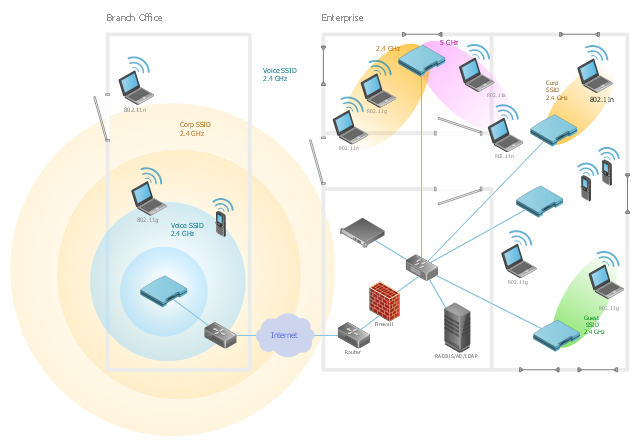
"A wireless local area network (WLAN) links two or more devices using some wireless distribution method (typically spread-spectrum or OFDM radio), and usually providing a connection through an access point to the wider Internet. This gives users the ability to move around within a local coverage area and still be connected to the network. Most modern WLANs are based on IEEE 802.11 standards, marketed under the Wi-Fi brand name. WLANs were once called LAWNs (for local area wireless network) by the Department of Defense." [Wireless LAN. Wikipedia]
The example "Wireless network diagram - Ultra high performance WLANs" was created using the ConceptDraw PRO diagramming and vector drawing software extended with the Wireless Networks solution from the Computer and Networks area of ConceptDraw Solution Park.
The example "Wireless network diagram - Ultra high performance WLANs" was created using the ConceptDraw PRO diagramming and vector drawing software extended with the Wireless Networks solution from the Computer and Networks area of ConceptDraw Solution Park.
WLAN diagram
Network Glossary Definition

This vector stencils library contains 184 round icons.
Use it to design cloud computing infographics and diagrams with ConceptDraw PRO software.
"Though service-oriented architecture advocates "everything as a service" (with the acronyms EaaS or XaaS or simply aas), cloud-computing providers offer their "services" according to different models, which happen to form a stack: infrastructure-, platform- and software-as-a-service.
Infrastructure as a service (IaaS)
In the most basic cloud-service model ... providers of IaaS offer computers — physical or (more often) virtual machines — and other resources. IaaS refers to online services that abstract the user from the details of infrastructure like physical computing resources, location, data partitioning, scaling, security, backup etc.
Platform as a service (PaaS)
PaaS vendors offer a development environment to application developers. The provider typically develops toolkit and standards for development and channels for distribution and payment. In the PaaS models, cloud providers deliver a computing platform, typically including operating system, programming-language execution environment, database, and web server. Application developers can develop and run their software solutions on a cloud platform without the cost and complexity of buying and managing the underlying hardware and software layers.
Software as a service (SaaS)
In the software as a service (SaaS) model, users gain access to application software and databases. Cloud providers manage the infrastructure and platforms that run the applications. SaaS is sometimes referred to as "on-demand software" and is usually priced on a pay-per-use basis or using a subscription fee.
In the SaaS model, cloud providers install and operate application software in the cloud and cloud users access the software from cloud clients. Cloud users do not manage the cloud infrastructure and platform where the application runs. This eliminates the need to install and run the application on the cloud user's own computers, which simplifies maintenance and support. Cloud applications differ from other applications in their scalability — which can be achieved by cloning tasks onto multiple virtual machines at run-time to meet changing work demand." [Cloud computing. Wikipedia]
The vector stencils library "Cloud round icons" is included in the Cloud Computing Diagrams solution from the Computer and Networks area of ConceptDraw Solution Park.
Add
Analysis
API
App
Archive
Back
Backup
Book
Books
Box
Bug
Calculation
Calendar
Call
Car
CD
Certificate
Cloud alert
Cloud analysis
Cloud authorization
Cloud collaboration
Cloud communications
Cloud computing
Cloud configuration
Cloud connectivity
Cloud control
Cloud cost calculation
Cloud database
Cloud download
Cloud drive
Cloud error
Cloud failure
Cloud FAQ
Cloud feedback
Cloud files
Cloud gateway
Cloud hosting
Cloud info
Cloud Internet storage
Cloud lock
Cloud locked
Cloud mail
Cloud music
Cloud paperless office
Cloud performance
Cloud photo
Cloud safe
Cloud search
Cloud security
Cloud servers
Cloud services
Cloud shopping
Cloud success
Cloud synchronization
Cloud tech support
Cloud transfer
Cloud unlocked
Cloud upload
Cloud video
Code
Collaboration
Communication
Community cloud
Contact list
Content
CPU
Database
Datacenter
Data storage
Desktop
Display
Document
Documents
Dollar
Done
Down
Download
E-commerce
Earth
Email
Encryption
Error
Ethernet
Euro
Failure
Feed
File
Files
Filter
Firewall
Flash drive
Folder
Forward
Hard drive
Hardware
Health
Health monitoring
Home
Hosting
Image
Info
Innovation
Key
Keyboard
Laptop
Letter
Lightning
Link
List
Location
Lock
Log
Login
Logout
Mail
Mail list
Marketplace
Memory (RAM)
Message
Minus
Mobile
Mobile cloud computing
Mouse
Music player
Network
Notebook
Notification
Package
Patch
Performance
Personal cloud
Phone book
Photo
Plug
Pound
Power
Power button
Process
Processing
Puzzles
Question sign
Recovery
Remote
Repair
Restore
Rocket (Logic app)
Router
Safety
Schedule
Script
SDK
Search (Scan)
Security
Server
Server rack
Services
Sharing
Shopping basket
Sign in
Smartphone
Song
Sound
Stethoscope
Stickman
Subscription
Sync
Tablet
Tech support
Time
Top rated
Transfer
Unlink
Unlock
Up
Upload
User
Video mail
View (visual)
Virus protection
Waste bin
Web
Wifi
Wireless
Yen sign
 Computer and Networks Area
The solutions from Computer and Networks Area of ConceptDraw Solution Park collect samples, templates and vector stencils libraries for drawing computer and network diagrams, schemes and technical drawings.
The vector stencils library "Computers and network isometric" contains 56 3D clipart images of computer and network devices and equipment for drawing network diagrams.
The clip art example "Computers and network isometric - Vector stencils library" was created using the ConceptDraw PRO diagramming and vector drawing software extended with the Computer and Networks solution from the Computer and Networks area of ConceptDraw Solution Park.
The clip art example "Computers and network isometric - Vector stencils library" was created using the ConceptDraw PRO diagramming and vector drawing software extended with the Computer and Networks solution from the Computer and Networks area of ConceptDraw Solution Park.
Laptop

DDCS

Server

Webcam

Wireless Network Storage

Personal computer

VoIP phone

Fax

Plotter

Mobile phone

Feature phone

Printer

Satellite dish

Satellite antenna

Automatic-tracking satellite dish
Wireless access point

Wireless router

Router

Network switch

Network device

Mobile GPS Terminal

GPS phone

Television antenna

Radio tower

Base station

Satellite

In-vehicle satellite telecommunication

Satellite dishes on ship

Airplane

Internet

Man

Woman

Call-center

Honeycomb

Mountain

Radio waves

Radio waves

Tower block

Office building

House

House

Globe

Wireless security camera

Truck

Tree

Conifer tree

1U hub / switch

2U hub / switch

1U server

2U Server

3U Server

4U Server

Communications satellite

Car

Radio waves

Firewall

The vector stencils library "Cisco network topology" contains 89 symbols of Cisco network devices and design elements for drawing computer network topology diagrams.
"There are two basic categories of network topologies:
(1) Physical topologies,
(2) Logical topologies.
The shape of the cabling layout used to link devices is called the physical topology of the network. This refers to the layout of cabling, the locations of nodes, and the interconnections between the nodes and the cabling. The physical topology of a network is determined by the capabilities of the network access devices and media, the level of control or fault tolerance desired, and the cost associated with cabling or telecommunications circuits.
The logical topology in contrast, is the way that the signals act on the network media, or the way that the data passes through the network from one device to the next without regard to the physical interconnection of the devices." [Network topology. Wikipedia]
The symbols example "Cisco network topology - Vector stencils library" was created using the ConceptDraw PRO diagramming and vector drawing software extended with the Cisco Network Diagrams solution from the Computer and Networks area of ConceptDraw Solution Park.
www.conceptdraw.com/ solution-park/ computer-networks-cisco
"There are two basic categories of network topologies:
(1) Physical topologies,
(2) Logical topologies.
The shape of the cabling layout used to link devices is called the physical topology of the network. This refers to the layout of cabling, the locations of nodes, and the interconnections between the nodes and the cabling. The physical topology of a network is determined by the capabilities of the network access devices and media, the level of control or fault tolerance desired, and the cost associated with cabling or telecommunications circuits.
The logical topology in contrast, is the way that the signals act on the network media, or the way that the data passes through the network from one device to the next without regard to the physical interconnection of the devices." [Network topology. Wikipedia]
The symbols example "Cisco network topology - Vector stencils library" was created using the ConceptDraw PRO diagramming and vector drawing software extended with the Cisco Network Diagrams solution from the Computer and Networks area of ConceptDraw Solution Park.
www.conceptdraw.com/ solution-park/ computer-networks-cisco
Router
Broadband router
Router firewall
Wireless router
Workgroup switch
ATM switch
ISDN switch
Multilayer switch
Protocol translator
Communications server
Transpath
Bridge
Terminal server
Route switch processor
Content engine (cache director)
Management engine (ME 1100)
Switch processor
ITP
Voice gateway
BBSM
ATA
SIP Proxy server
NetRanger
Cisco 1000
IP
System controller
ACE
Directory server
ADM
Cisco Unity Express
Unity server
Cisco security
CallManager
DSLAM
H.323
CDM (Content Distribution Manager)
ICM
Access point
Wireless bridge
Wireless connectivity
Guard
Mobile access router
Carrier Routing System (CRS)
Vault
Workstation
PC
Macintosh
Cloud, gold
Cloud, white
Cloud, standard color
Cisco security management
PBX
DPT
Government building
Headquarters, blue
Router in building
Man
Woman
Workgroup switch, subdued
Router, subdued
File server
Firewall, horizontal
Firewall, vertical
Firewall, vertical, subdued
Lock
Key
Lock and key
Car
Truck
File cabinet
Breakout box
Breakout box, blue
Host
Relational database
Modem
BBS (Bulletin Board System)
Satellite
Satellite dish
UPS
RPS
MAU
PAD
PAD X.28
Diskette
Contact center
Page icon
Antenna
Antenna, blue
Radio tower
- Wide area network (WAN) topology. Computer and Network Examples
- Internet symbols - Vector stencils library | Data Flow Diagram ...
- How To use Switches in Network Diagram | Star Network Topology ...
- Hotel Network Topology Diagram | Star Network Topology | Wireless ...
- Hardware Firewall
- Network Diagram Cloud Firewall Workstation Switch Server
- Network Diagram With Router And Firewall
- Building Drawing Design Element: Storage and Distribution | Interior ...
- Mobile satellite communication network diagram | Digital ...
- How To use Switches in Network Diagram | Star Network Topology ...
- Draw The Symbol For Distribution Board
- Router Firewall Switch Diagram
- VMware vNetwork Distributied Switch (vDS). Computer and Network ...
- Grid Computing Architecture Diagram
- Symbol For Distribution Board
- Internet symbols - Vector stencils library | Cloud Computing | Mobile ...
- Grid Computing Diagram
- Firewall Topology Diagram
- Switch Distribution
- Drawings Of The Distribution Board