This example of cloud computing system architecture diagram was redesigned from the Wikimedia Commons file: ArchitectureCloudLinksSameSite.png. [commons.wikimedia.org/ wiki/ File:ArchitectureCloudLinksSameSite.png]
"An example showing a grid computing system connecting many personal computers over the Internet using inter-process network communication ...
In computer science, inter-process communication (IPC) is the activity of sharing data across multiple and commonly specialized processes using communication protocols. Typically, applications using IPC are categorized as clients and servers, where the client requests data and the server responds to client requests." [en.wikipedia.org/ wiki/ Inter-process_ communication]
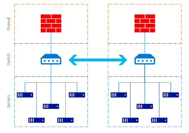
"Grid computing is the collection of computer resources from multiple locations to reach a common goal. The grid can be thought of as a distributed system with non-interactive workloads that involve a large number of files. Grid computing is distinguished from conventional high performance computing systems such as cluster computing in that grid computers have each node set to perform a different task/ application. Grid computers also tend to be more heterogeneous and geographically dispersed (thus not physically coupled) than cluster computers." [Grid computing. Wikipedia]
The diagram example "Grid computing system architecture" was created using ConceptDraw PRO diagramming and vector drawing software extended with the Azure Architecture solution from the Computer and Networks area of ConceptDraw Solution Park.
"An example showing a grid computing system connecting many personal computers over the Internet using inter-process network communication ...
In computer science, inter-process communication (IPC) is the activity of sharing data across multiple and commonly specialized processes using communication protocols. Typically, applications using IPC are categorized as clients and servers, where the client requests data and the server responds to client requests." [en.wikipedia.org/ wiki/ Inter-process_ communication]
"Grid computing is the collection of computer resources from multiple locations to reach a common goal. The grid can be thought of as a distributed system with non-interactive workloads that involve a large number of files. Grid computing is distinguished from conventional high performance computing systems such as cluster computing in that grid computers have each node set to perform a different task/ application. Grid computers also tend to be more heterogeneous and geographically dispersed (thus not physically coupled) than cluster computers." [Grid computing. Wikipedia]
The diagram example "Grid computing system architecture" was created using ConceptDraw PRO diagramming and vector drawing software extended with the Azure Architecture solution from the Computer and Networks area of ConceptDraw Solution Park.
Grid computing system architecture diagram
Cisco IBM. Cisco icons, shapes, stencils and symbols
")
 Computer Network Diagrams
Computer Network Diagrams solution extends ConceptDraw PRO software with samples, templates and libraries of vector icons and objects of computer network devices and network components to help you create professional-looking Computer Network Diagrams, to plan simple home networks and complex computer network configurations for large buildings, to represent their schemes in a comprehensible graphical view, to document computer networks configurations, to depict the interactions between network's components, the used protocols and topologies, to represent physical and logical network structures, to compare visually different topologies and to depict their combinations, to represent in details the network structure with help of schemes, to study and analyze the network configurations, to communicate effectively to engineers, stakeholders and end-users, to track network working and troubleshoot, if necessary.
UML Diagram

 Cisco Network Diagrams
Cisco Network Diagrams solution extends ConceptDraw PRO with the best characteristics of network diagramming software. Included samples, templates and libraries of built-in standardized vector Cisco network icons and Cisco symbols of computers, network devices, network appliances and other Cisco network equipment will help network engineers, network designers, network and system administrators, as well as other IT professionals and corporate IT departments to diagram efficiently the network infrastructure, to visualize computer networks topologies, to design Cisco computer networks, and to create professional-looking Cisco Computer network diagrams, Cisco network designs and schematics, Network maps, and Network topology diagrams in minutes.
 AWS Architecture Diagrams
AWS Architecture Diagrams with powerful drawing tools and numerous predesigned Amazon icons and AWS simple icons is the best for creation the AWS Architecture Diagrams, describing the use of Amazon Web Services or Amazon Cloud Services, their application for development and implementation the systems running on the AWS infrastructure. The multifarious samples give you the good understanding of AWS platform, its structure, services, resources and features, wide opportunities, advantages and benefits from their use; solution’s templates are essential and helpful when designing, description and implementing the AWS infrastructure-based systems. Use them in technical documentation, advertising and marketing materials, in specifications, presentation slides, whitepapers, datasheets, posters, etc.
This rack diagram example was drawn on the base of picture illustrating the article "Virtualization in general, for technicans and business people" from the Banym's Blog by Dominik Zajac. [banym.de/ virtualization/ virtualization-in-general-for-technicans-and-business-people]
"Virtualization, in computing, refers to the act of creating a virtual (rather than actual) version of something, including but not limited to a virtual computer hardware platform, operating system (OS), storage device, or computer network resources." [Virtualization. Wikipedia]
"With the CPUs we have today you can virtualize up to 10 – 12 old servers to one new big machine with for example 2 x 6 core CPUs and a lot of memory. In this case you see what potential this technology has. Turn off 10 servers and run it on just one machine. That’s not the way I would do Virtualization. It’s nice to save energy but what happens if we have a problem with our one new big server? The complete organization can not work without ERP, EMail etc. and because of this we need a cluster.
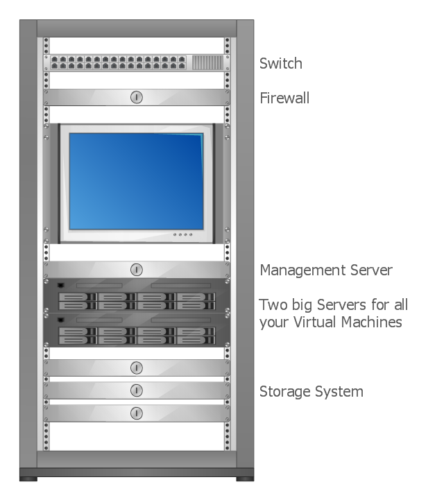
Such a cluster configuration looks something like this: (rack diagram example).
Two big servers, a storage subsystem and a smaller management server. If you compare now the old configuration with the new one you can see there will be still made some points for energy efficiency. That’s not the only benefit you should have in focus, for the mature Virtualization solutions like VMware or Citrix/ XEN exist a big number of tools and documentation to make the life easier for administrators and system managers. This safes time and brings better reaction times for your IT." [banym.de/ virtualization/ virtualization-in-general-for-technicans-and-business-people]
The rack diagram example "Virtualized computer center" was created using the ConceptDraw PRO diagramming and vector drawing software extended with the Rack Diagrams solution from the Computer and Networks area of ConceptDraw Solution Park.
"Virtualization, in computing, refers to the act of creating a virtual (rather than actual) version of something, including but not limited to a virtual computer hardware platform, operating system (OS), storage device, or computer network resources." [Virtualization. Wikipedia]
"With the CPUs we have today you can virtualize up to 10 – 12 old servers to one new big machine with for example 2 x 6 core CPUs and a lot of memory. In this case you see what potential this technology has. Turn off 10 servers and run it on just one machine. That’s not the way I would do Virtualization. It’s nice to save energy but what happens if we have a problem with our one new big server? The complete organization can not work without ERP, EMail etc. and because of this we need a cluster.
Such a cluster configuration looks something like this: (rack diagram example).
Two big servers, a storage subsystem and a smaller management server. If you compare now the old configuration with the new one you can see there will be still made some points for energy efficiency. That’s not the only benefit you should have in focus, for the mature Virtualization solutions like VMware or Citrix/ XEN exist a big number of tools and documentation to make the life easier for administrators and system managers. This safes time and brings better reaction times for your IT." [banym.de/ virtualization/ virtualization-in-general-for-technicans-and-business-people]
The rack diagram example "Virtualized computer center" was created using the ConceptDraw PRO diagramming and vector drawing software extended with the Rack Diagrams solution from the Computer and Networks area of ConceptDraw Solution Park.
Rack diagram
 Azure Architecture
Azure Architecture solution bundles into one handy tool everything you need to create effective Azure Architecture diagrams. It adds the extra value to versatile ConceptDraw PRO software and extends the users capabilities with comprehensive collection of Microsoft Azure themed graphics, logos, preset templates, wide array of predesigned vector symbols that covers the subjects such as Azure management, Azure storage, and Azure services, amongst others, and allow you to illustrate Azure Architecture diagrams at any degree of complexity, to present visually your Azure cloud system architecture with professional style, to design Azure cloud topology, to document Windows Azure Architecture and Azure Cloud System Architecture, to visualize the great abilities and work of Microsoft Azure Cloud System and Azure services.
Cisco LAN. Cisco icons, shapes, stencils and symbols
")
 Google Cloud Platform
Google Cloud Platform solution extends the ConceptDraw PRO functionality with extensive collection of drawing tools, ready-made samples and professionally designed specific Google Cloud Platform icons, allowing effectively design Google Cloud Platform (GCP) architectural diagrams, Google Cloud Platform drawings, GCP schematics of different complexity, and to illustrate on them the work of Google Cloud Platform (GCP), best features of GCP, its services, solutions and products, and the ways of their use.
- Cluster Computing Architecture Diagram
- Diagram For Cluster Computing
- Cluster Computing Easy Diagram
- Cluster Architecture Diagram
- Grid Computing With Diagram
- Azure Architecture | How Internet Process Cluster Diagrams
- What Is The Purpose Of A Web Or Cluster Diagram
- What Is A Web Or Cluster Diagram
- Grid Computing Diagram