Example of DFD for Online Store (Data Flow Diagram)


Data Flow Diagram Model

UML Component Diagram Example - Online Shopping

Interaction Overview Diagram


Data Flow Diagrams

Structured Systems Analysis and Design Method (SSADM) with ConceptDraw DIAGRAM

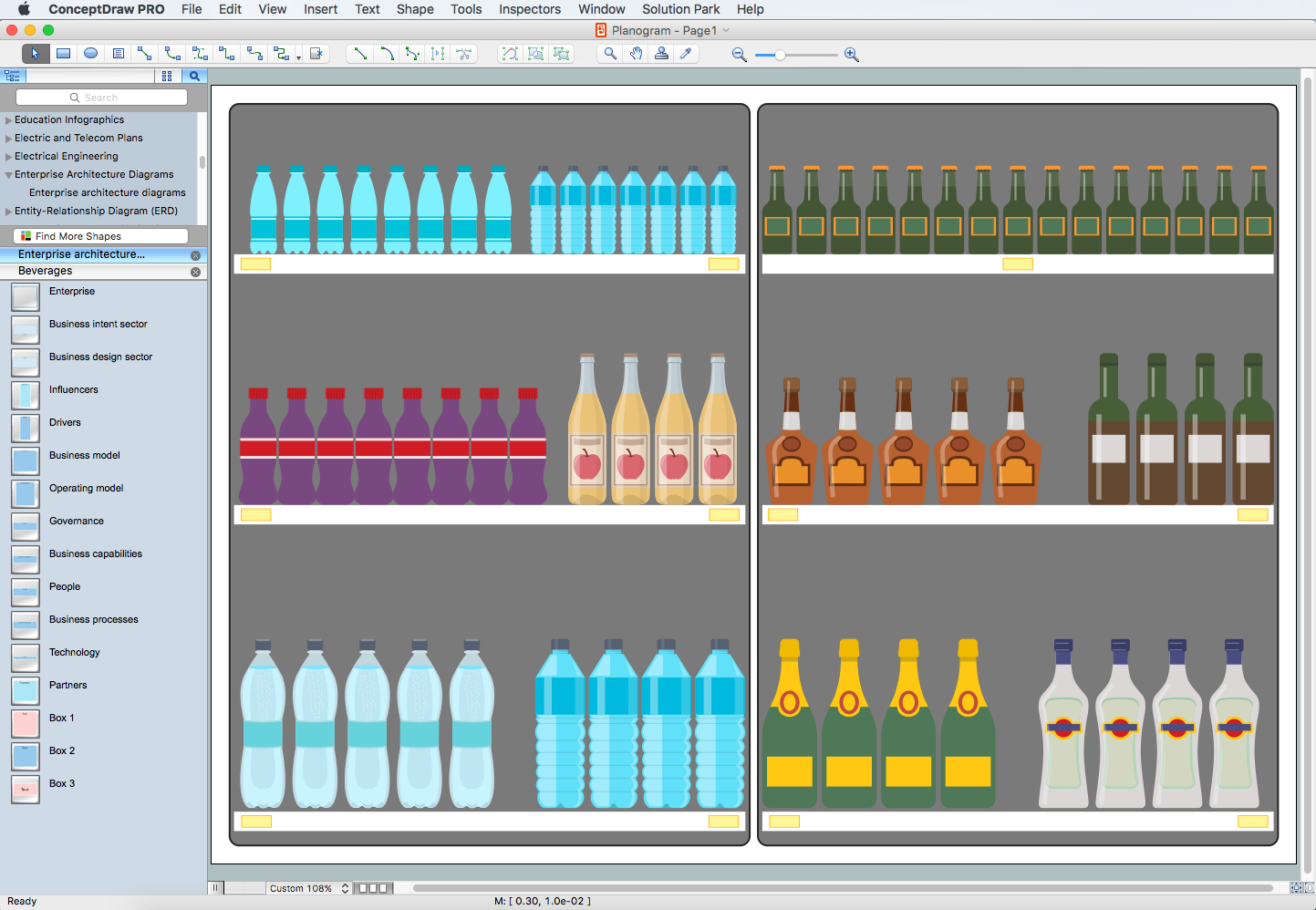
Planogram Software and Retail Plan Software
 Presentation Exchange
This solution extends ConceptDraw MINDMAP software with the ability to import presentations from Microsoft PowerPoint, as well as enhancing its existing presentation capabilities.
- Data Flow Diagram For Online Shopping System Level 0 1 2
- Level 1 Dfd Diagram For Online Shopping System
- Dfd Level 2 For Online Shopping
- Level 1 Dfd Of Online Shopping
- Online Shopping Level 0 Level1 Level2 Dfd
- Dfd Level 0 Level 1 Level 2 Examples
- Level 1 Dfd For Online Shopping System
- IDEF0 Diagrams | Level 0 Dfd Diagram For Online Shopping
- Draw All Levels Of Dfd For Online Book Shopping
- What Is Level 0 Level 1 Level 2 Data Flow Diagram