 ATM UML Diagrams
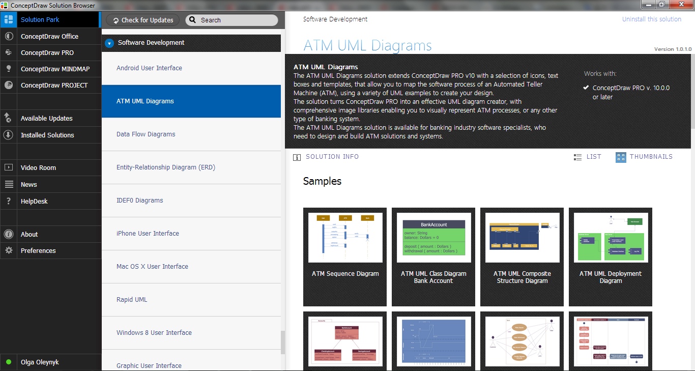
The ATM UML Diagrams solution lets you create ATM solutions and UML examples. Use ConceptDraw DIAGRAM as a UML diagram creator to visualize a banking system.
ATM Solutions
ATM Network. Computer and Network Examples


UML Deployment Diagram Example - ATM System UML diagrams

 Data Flow Diagrams (DFD)
Data Flow Diagrams solution extends ConceptDraw DIAGRAM software with templates, samples and libraries of vector stencils for drawing the data flow diagrams (DFD).
UML Use Case Diagram Example. Services UML Diagram. ATM system

UML Diagram

 Entity-Relationship Diagram (ERD)
An Entity-Relationship Diagram (ERD) is a visual presentation of entities and relationships. That type of diagrams is often used in the semi-structured or unstructured data in databases and information systems. At first glance ERD is similar to a flowch
Yourdon and Coad Diagram

Design Elements for UML Diagrams

 Business Process Diagrams
Business Process Diagrams solution extends the ConceptDraw DIAGRAM BPM software with RapidDraw interface, templates, samples and numerous libraries based on the BPMN 1.2 and BPMN 2.0 standards, which give you the possibility to visualize equally easy simple and complex processes, to design business models, to quickly develop and document in details any business processes on the stages of project’s planning and implementation.
 Scatter Diagrams
The Scatter Diagrams solution extends ConceptDraw DIAGRAM functionality with templates, samples, and a library of vector stencils that make construction of a Scatter Plot easy. The Scatter Chart Solution makes it easy to design attractive Scatter Diagrams used in various fields of science, work, and life activities. ConceptDraw DIAGRAM lets you enter the data to the table and construct the Scatter Plot Graph automatically according to these data.
Entity Relationship Diagram - ERD - Software for Design Crows Foot ER Diagrams
_Win_Mac.png)

- UML activity diagram - Cash withdrawal from ATM | UML Activity ...
- Entity Relationship Diagram Of Atm Machine System
- Data Flow Diagrams (DFD) | ATM UML Diagrams | DFD Library ...
- ATM System UML diagrams
- Er Diagram For Atm System
- Data Flow Diagram Of Atm Machine In Software Engineering
- ATM Solutions | Entity -Relationship Diagram (ERD) | Entity ...
- Entity -Relationship Diagram (ERD) | ATM Solutions | Entity ...
- Data Flow Diagram For Atm Banking System
- ATM Solutions | Data Flow Diagrams (DFD) | DFD Library System ...
- State Diagram Of Atm Machine
- ATM Solutions | Entity -Relationship Diagram (ERD) | Entity ...
- Atm Machine Process Flow Block Diagram Download
- Entity -Relationship Diagram (ERD) | ATM Solutions | Entity ...
- DFD Library System | ATM UML Diagrams | Data Flow Diagram | Dfd ...
- Er Diagram For Atm Management System
- Draw A Flowchart How To Atm Machine Works
- ATM UML Diagrams | Model Based Systems Engineering | Entity ...
- UML Activity Diagram | ATM UML Diagrams | ATM Solutions | Draw ...