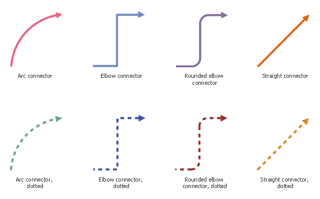
The vector stencils library "Workflow connectors" contains 8 flow lines.
Use it to design your business process workflow diagrams with ConceptDraw PRO software.
"A flowchart is a type of diagram that represents an algorithm, workflow or process, showing the steps as boxes of various kinds, and their order by connecting them with arrows. ...
Flow Line ... An arrow coming from one symbol and ending at another symbol represents that control passes to the symbol the arrow points to. The line for the arrow can be solid or dashed. The meaning of the arrow with dashed line may differ from one flowchart to another and can be defined in the legend." [Flowchart. Wikipedia]
The flowchart arrows example "Design elements - Workflow connectors" is included in the Business Process Workflow Diagrams solution from the Business Processes area of ConceptDraw Solution Park.
Flow lines
ERD Symbols and Meanings


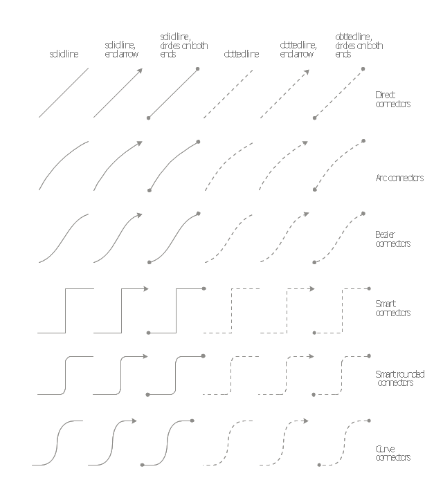
The vector stencils library "Management connectors" contains 36 connector shapes: solid and dotted lines with or without arrows or circles on the ends.
Use it to illustrate your management infograms with block diagrams.
"Block diagram is a diagram of a system in which the principal parts or functions are represented by blocks connected by lines that show the relationships of the blocks." [Block diagram. Wikipedia]
The shapes example "Design elements - Management connectors" was created using the ConceptDraw PRO diagramming and vector drawing software extended with the Management Infographics solition from the area "Business Infographics" in ConceptDraw Solution Park.
Connectors
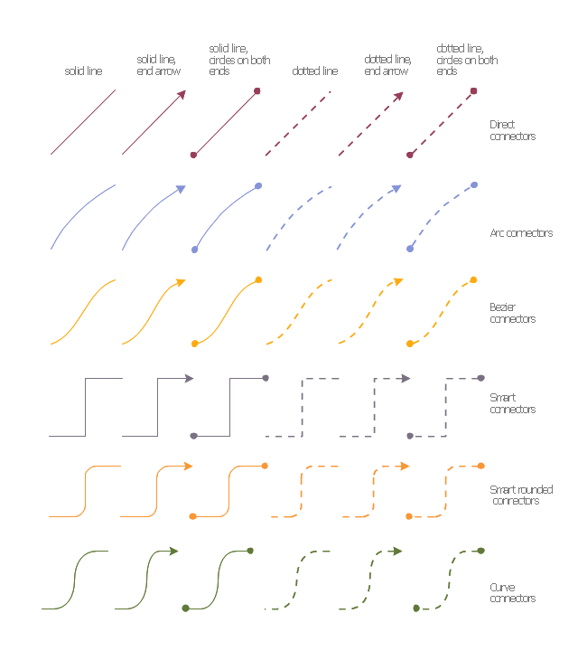
The vector stencils library "Financial connectors" contains 36 connection lines and arrows.
Connectors, or connection lines and arrows are used to connect shapes in diagrams and infographic visuals.
Use it to design your financial infographics.
Connectors, or connection lines and arrows are used to connect shapes in diagrams and infographic visuals.
Use it to design your financial infographics.
Infographic elements
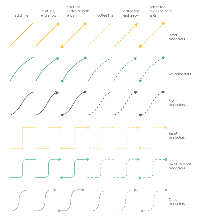
The vector stencils library "Education connectors" contains 36 connector shapes: solid and dotted lines with or without arrows or circles on the ends.
Use it to illustrate your education infograms with block diagrams.
"Block diagram is a diagram of a system in which the principal parts or functions are represented by blocks connected by lines that show the relationships of the blocks." [Block diagram. Wikipedia]
The shapes example "Design elements - Education connectors" was created using the ConceptDraw PRO diagramming and vector drawing software extended with the Education Infographics solition from the area "Business Infographics" in ConceptDraw Solution Park.
Connectors
Entity Relationship Diagram Symbols

Basic Flowchart Symbols and Meaning


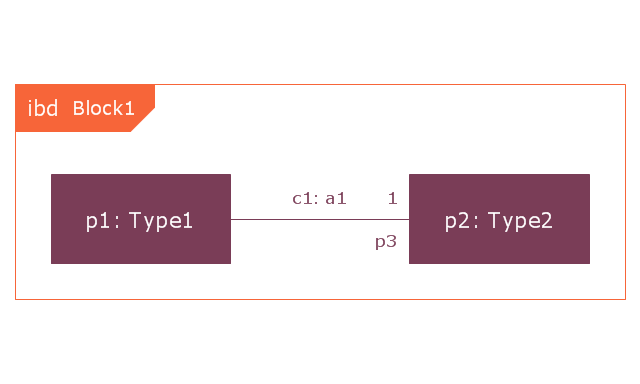
This vector stencils library contains 22 IBD symbols.
Use it to design your internal block diagrams using ConceptDraw PRO diagramming and vector drawing software.
"Internal Block Diagram
An internal block diagram is based on the UML composite structure diagram, with restrictions and extensions as defined
by SysML. ...
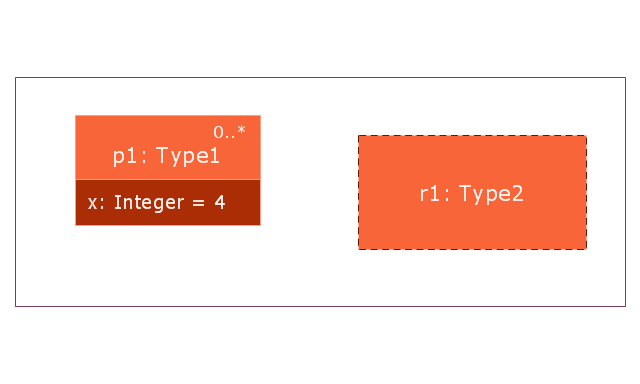
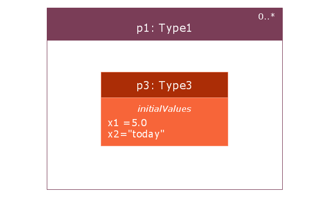
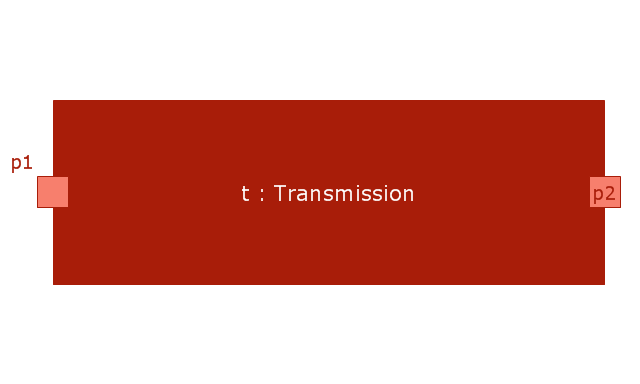
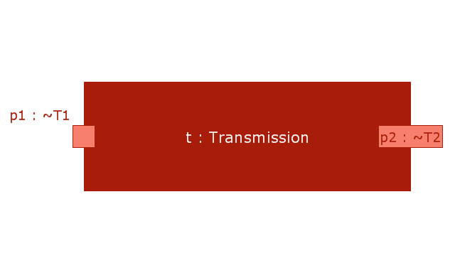
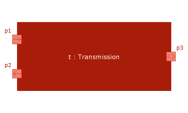
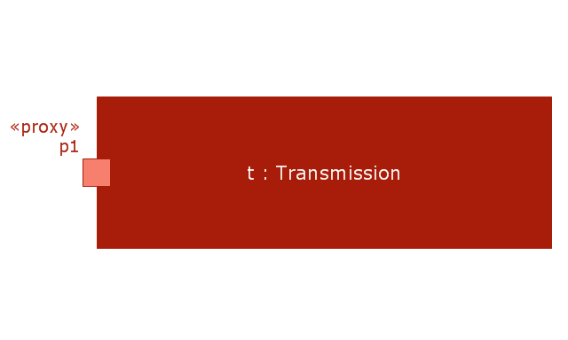
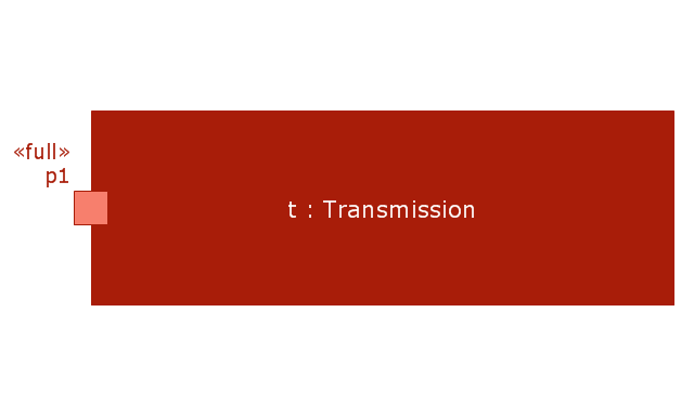
Property types
Four general categories of properties of blocks are recognized in SysML: parts, references, value properties, and
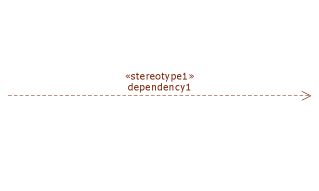
constraint properties. ... A part or value property is always shown on an internal block diagram with a solid-outline box. A reference property is shown by a dashed-outline box, consistent with UML. Ports are special cases of properties, and have a variety of notations... Constraint properties and their parameters also have their own notations... " [www.omg.org/ spec/ SysML/ 1.3/ PDF]
The vector stencils library "Internal block diagram" is included in the SysML solution from the Software Development area of ConceptDraw Solution Park.
Use it to design your internal block diagrams using ConceptDraw PRO diagramming and vector drawing software.
"Internal Block Diagram
An internal block diagram is based on the UML composite structure diagram, with restrictions and extensions as defined
by SysML. ...
Property types
Four general categories of properties of blocks are recognized in SysML: parts, references, value properties, and
constraint properties. ... A part or value property is always shown on an internal block diagram with a solid-outline box. A reference property is shown by a dashed-outline box, consistent with UML. Ports are special cases of properties, and have a variety of notations... Constraint properties and their parameters also have their own notations... " [www.omg.org/ spec/ SysML/ 1.3/ PDF]
The vector stencils library "Internal block diagram" is included in the SysML solution from the Software Development area of ConceptDraw Solution Park.
Internal block diagram
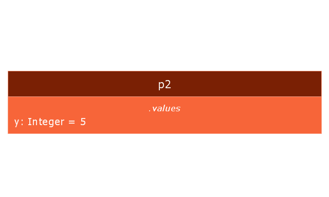
Property
Property 2
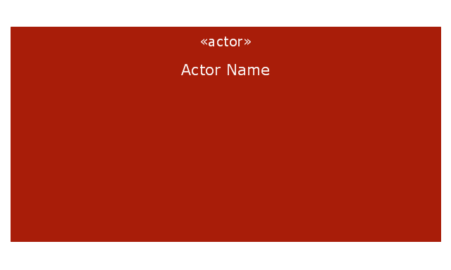
Actor part
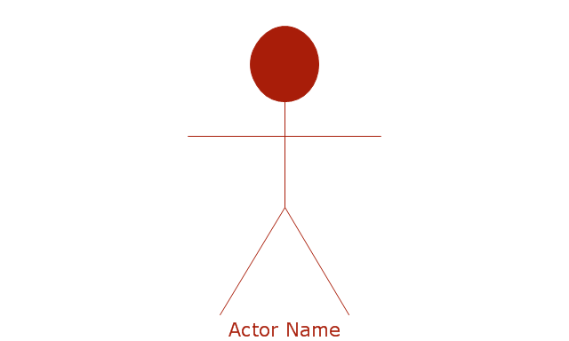
Actor part 2
Property specific type
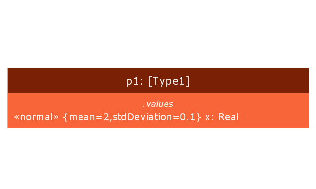
Property specific type 2
Dependency
Binding connector
Binding connector, equal
Bidirectional connector
Unidirectional connector
Conjugated ports
Conjugated ports 2
Ports with flow properties
Port (nested)
-vector-stencils-library---internal-block-diagram.png--diagram-flowchart-example.png)
Proxy port
Full port
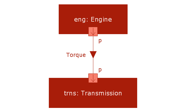
Item flow
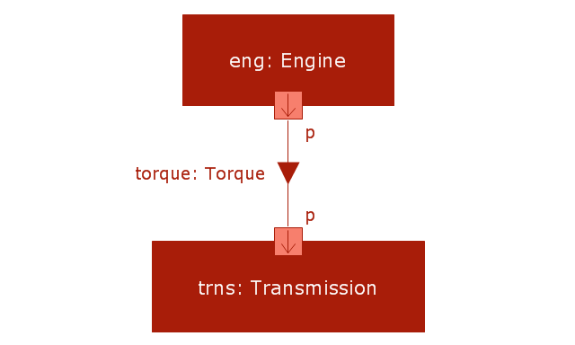
Item flow with an item property
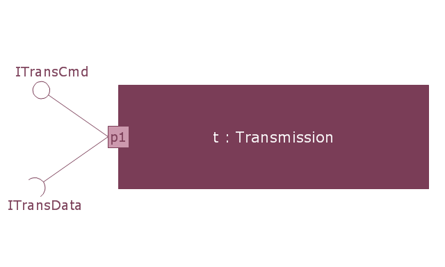
Required and provided interfaces
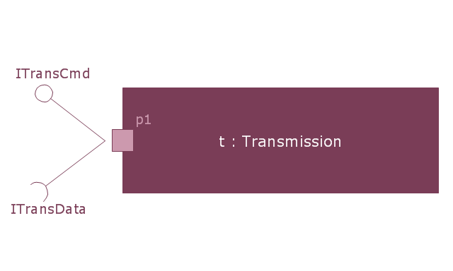
Required and provided interfaces 2
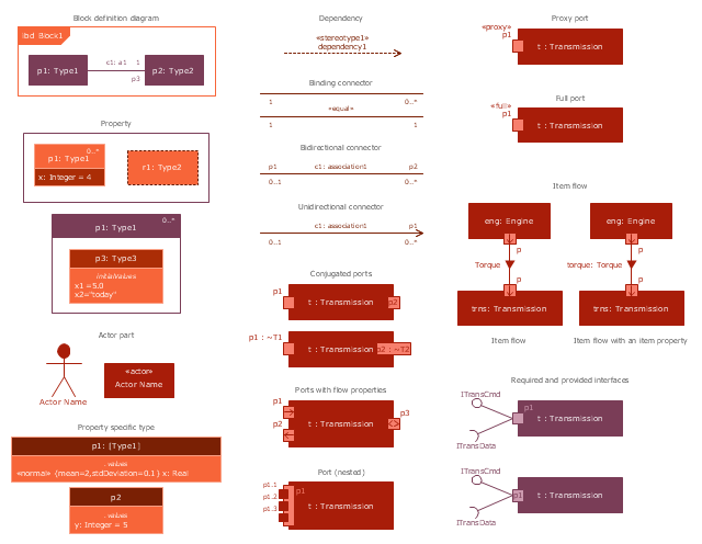
The vector stencils library "Internal block diagram" contains 22 SysML symbols.
Use it to design your internal block diagrams using ConceptDraw PRO diagramming and vector drawing software.
"Internal Block Diagram
An internal block diagram is based on the UML composite structure diagram, with restrictions and extensions as defined
by SysML. ...
Property types
Four general categories of properties of blocks are recognized in SysML: parts, references, value properties, and
constraint properties. ... A part or value property is always shown on an internal block diagram with a solid-outline box. A reference property is shown by a dashed-outline box, consistent with UML. Ports are special cases of properties, and have a variety of notations... Constraint properties and their parameters also have their own notations... " [www.omg.org/ spec/ SysML/ 1.3/ PDF]
The SysML shapes example "Design elements - Internal block diagram" is included in the SysML solution from the Software Development area of ConceptDraw Solution Park.
Internal block diagram symbols
The Best Tool for Business Process Modeling

- Dotted Line Connectors
- Dashed Straight Arrow
- Design elements - Workflow connectors | Firewall between LAN and ...
- Meaning Of Dotted Line In Er Diagram
- Dotted Line In Flowchart Meaning
- Design elements - Management connectors
- Design elements - Marketing connectors
- Design elements - Education connectors
- Design elements - Financial connectors
- Design elements - Workflow connectors | Garrett IA Diagrams with ...