Collaboration in a Project Team

"A deke is an ice hockey technique which a player uses to get past an opponent or "fake out" an opposing player. The term is a Canadianism formed by abbreviating decoy.
The deke may originally have referred to quickly pushing the puck forward or laterally with the forehand and catching it on the backhand (or vice-versa), but as hockey has evolved so has the deke and it is now used to refer to a wide variety of feints, fakes or skillful maneuvers to beat defenders or goaltenders. The position of the player performing the deke and the opponent determines where the puck will be moved and the speed. The deke can be used to move the puck out of reach of an opposing player, move the puck past the opposing player, or quickly change direction of the puck so the opposing player is caught out of position. Dekes are usually used in combination with either a change of direction or speed, or both; the deke may refer to the entire sequence of actions as well as the maneuver(s) made with the stick. Often a change in direction or a change in speed is enough to get past an opposing player, but dekes are used in combination with these to better protect the puck and get by a defender." [Deke (ice hockey). Wikipedia]
The ice hockey tactic diagram example "Deke (ice hockey)" was created using the ConceptDraw PRO diagramming and vector drawing software extended with the Hockey solution from the Sport area of ConceptDraw Solution Park.
Ice hockey tactic diagram
.png--diagram-flowchart-example.png)
 Health Food
The Health Food solution contains the set of professionally designed samples and large collection of vector graphic libraries of healthy foods symbols of fruits, vegetables, herbs, nuts, beans, seafood, meat, dairy foods, drinks, which give powerful possi
This circular arrows diagram sample shows the systems development life cycle (SDLC) stages.
"The systems development life cycle (SDLC), also referred to as the application development life-cycle, is a term used in systems engineering, information systems and software engineering to describe a process for planning, creating, testing, and deploying an information system. The systems development life-cycle concept applies to a range of hardware and software configurations, as a system can be composed of hardware only, software only, or a combination of both." [Systems development life-cycle. Wikipedia]
The arrow circle diagram example "Systems development life cycle" was created using the ConceptDraw PRO diagramming and vector drawing software extended with the Circular Arrows Diagrams solution from the area "What is a Diagram" of ConceptDraw Solution Park.
Circular arrows diagram

 Cooking Recipes
Create quick and easy recipe diagrams with the Cooking Recipes solution. Make a tasty meal for dinner, for holidays, or for a party.
HelpDesk
How to Resize Objects in ConceptDraw PRO

HelpDesk
How to Perform Presentations in ConceptDraw MINDMAP without Exporting to Other Applications

This cafe electrical floor plan sample shows the outlet and switch layout.
"An electrical drawing, is a type of technical drawing that shows information about power, lighting, and communication for an engineering or architectural project. Any electrical working drawing consists of "lines, symbols, dimensions, and notations to accurately convey an engineering's design to the workers, who install the electrical system on the job".
A complete set of working drawings for the average electrical system in large projects usually consists of:
(1) A plot plan showing the building's location and outside electrical wiring.
(2) Floor plans showing the location of electrical systems on every floor.
(3) Power-riser diagrams showing panel boards.
(4) Control wiring diagrams.
(5) Schedules and other information in combination with construction drawings.
Electrical drafters prepare wiring and layout diagrams used by workers who erect, install, and repair electrical equipment and wiring in communication centers, power plants, electrical distribution systems, and buildings." [Electrical drawing. Wikipedia]
The outlet and switch layout example "Cafe electrical floor plan" was created using the ConceptDraw PRO diagramming and vector drawing software extended with the Electric and Telecom Plans solution from the Building Plans area of ConceptDraw Solution Park.
Outlet and switch layout

ConceptDraw Arrows10 Technology

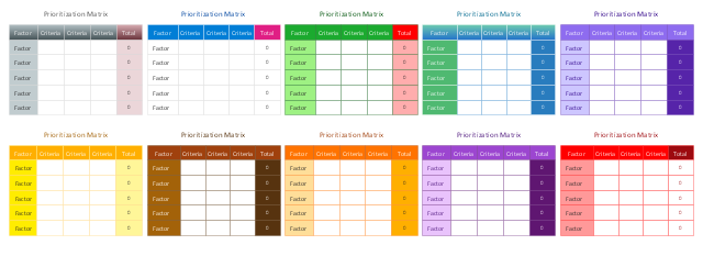
This vector stencils library contains 10 templates for drawing the prioritization matrices using the ConceptDraw PRO diagramming and vector drawing software.
The prioritization matrix is one of the Seven Management and Planning Tools (7 MP tools, Seven New Quality Tools).
"Prioritization Matrix ... is used to prioritize items and describe them in terms of weighted criteria. It uses a combination of tree and matrix diagramming techniques to do a pair-wise evaluation of items and to narrow down options to the most desired or most effective. Popular applications for the Prioritization Matrix include Return-on-Investment (ROI) or Cost-Benefit analysis (Investment vs. Return), Time management Matrix (Urgency vs. Importance), etc." [Seven Management and Planning Tools. Wikipedia]
Use prioritization matrix to rank items based on a set of criteria.
The example "Design elements - Prioritization matrix" is included in the solution "Seven Management and Planning Tools" from the Management area of ConceptDraw Solution Park.
Prioritization matrices
The vector stencils library "Qualifying" contains 56 qualifying symbols of radiation, polarity, phase, windings, wire, ground, connection, connector, coaxial, electret.
Use these signs to annotate or specify characteristics of objects in electrical drawings, electronic schematics, circuit diagrams, electromechanical drawings, and wiring diagrams, cabling layout diagrams.
"An electrical drawing, is a type of technical drawing that shows information about power, lighting, and communication for an engineering or architectural project. Any electrical working drawing consists of "lines, symbols, dimensions, and notations to accurately convey an engineering's design to the workers, who install the electrical system on the job".
A complete set of working drawings for the average electrical system in large projects usually consists of:
(1) A plot plan showing the building's location and outside electrical wiring.
(2) Floor plans showing the location of electrical systems on every floor.
(3) Power-riser diagrams showing panel boards.
(4) Control wiring diagrams.
(5) Schedules and other information in combination with construction drawings.
Electrical drafters prepare wiring and layout diagrams used by workers who erect, install, and repair electrical equipment and wiring in communication centers, power plants, electrical distribution systems, and buildings." [Electrical drawing. Wikipedia]
The signs example "Design elements - Qualifying" was drawn using the ConceptDraw PRO diagramming and vector drawing software extended with the Electrical Engineering solution from the Engineering area of ConceptDraw Solution Park.
Qualifying symbols

- Pyramid Chart Examples | Business Productivity Area | Product ...
- PROBLEM ANALYSIS. Prioritization Matrix | Prioritization matrix ...
- Prioritization matrix template | Seven Management and Planning ...
- Offside (ice hockey) | Deke (ice hockey) | Soccer (Football) Tactics ...
- Computer peripheral devices - Vector stencils library
- Timeline Diagrams | Gantt Chart Software | How to Report Task's ...
- Social Media Response Management Action Maps - software tool ...
- SWOT Analysis Solution - Strategy Tools | SWOT and TOWS Matrix ...
- PROBLEM ANALYSIS Prioritization Matrix | Seven Management and ...
- Provide Team Training | Social Media Response Management ...
- Social Media Response Flowcharts - diagramming software ( Mac ...
- Industrial vehicles - Vector stencils library | Industrial vehicles ...
- How to Create a Social Media Flowchart | What is SWOT Analysis in ...
- Seven Management and Planning Tools | PROBLEM ANALYSIS ...
- 3 Circle Venn Diagram. Venn Diagram Example
- Social Media Response Management Action Maps - software tool ...
- Seven Management and Planning Tools | Design elements ...
- Security system plan
- Porter's value chain matrix diagram
- How To use House Electrical Plan Software | Cafe electrical floor ...