Electrical Symbols, Electrical Schematic Symbols

How To use House Electrical Plan Software


Electrical Symbols, Electrical Diagram Symbols

The vector stencils library "IDEF3 process schematic symbols" contains 12 shapes: unit of behavior (UOB), links, junctions, .
Use it to design your IDEF3 process schematic diagrams.
"Process schematics tend to be the most familiar and broadly used component of the IDEF3 method. These schematics provide a visualization mechanism for processcentered descriptions of a scenario. The graphical elements that comprise process schematics include Unit of Behavior (UOB) boxes, precedence links, junctions, referents, and notes. The building blocks here are:
- Unit of Behavior (UOB) boxes.
- Links: Links are the glue that connect UOB boxes to form representations of dynamic processes.
- Simple Precedence Links: Precedence links express temporal precedence relations between instances of one UOB and those of another.
- Activation Plots: Activation plots are used to represent activations.
- Dashed Links: Dashed links carry no predefined semantics.
- Link Numbers: All links have an elaboration and unique link numbers.
Activation Semantics for Nonbranching Process Schematics.
- Junctions: Junctions in IDEF3 provide a mechanism to specify the logic of process branching.
- UOB Decompositions: Elaborations capture and structure detailed knowledge about processes.
- UOB Reference Numbering Scheme: A UOB box number is assigned to each UOB box in an IDEF3 Process Description.
- Partial Descriptions: UOB boxes are joined together by links. Because of the description capture focus of IDEF3, it is possible to conceive of UOBs without links to other parts of an IDEF3 schematic.
- Referents: Referents enhance understanding, provide additional meaning, and simplify the construction (i.e., minimize clutter) of both process schematics and object schematics." [IDEF3. Wikipedia]
The shapes example "Design elements - IDEF3 process schematic symbols" was created using the ConceptDraw PRO diagramming and vector drawing software extended with the solution "IDEF Business Process Diagrams" from the area "Business Processes" of ConceptDraw Solution Park.
IDEF3 business process diagram

This vector stencils library contains 12 object schematic symbols.
Use it to design your IDEF3 diagrams with ConceptDraw PRO diagramming and vector drawing tools.
The vector stencils library "IDEF3 object schematic symbols" is included in the IDEF Business Process Diagrams solution from the Business Processes area of ConceptDraw Solution Park.
Use it to design your IDEF3 diagrams with ConceptDraw PRO diagramming and vector drawing tools.
The vector stencils library "IDEF3 object schematic symbols" is included in the IDEF Business Process Diagrams solution from the Business Processes area of ConceptDraw Solution Park.
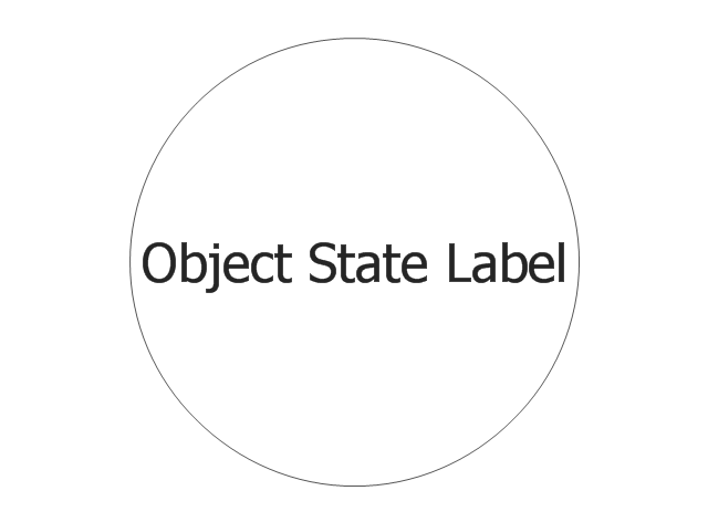
Object
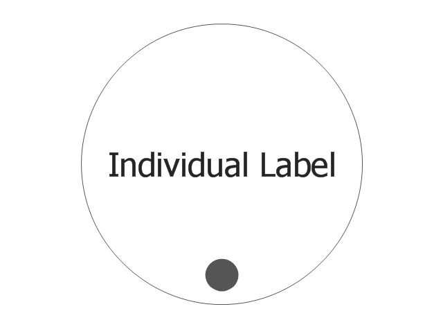
Individual
Weak Transition Link

Strong Transition Link

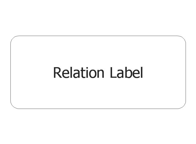
n-Place 1st-order Relation
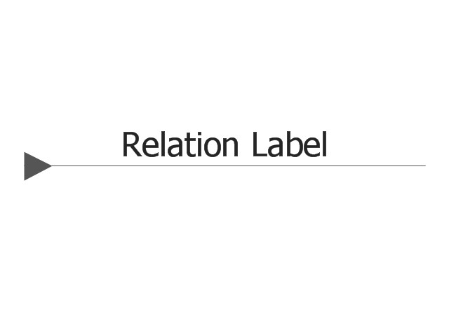
2-Place 2nd-order Relation
AND Junction (object)
-vector-stencils-library---idef3-object-schematic-symbols.png--diagram-flowchart-example.png)
OR Junction (object)
-vector-stencils-library---idef3-object-schematic-symbols.png--diagram-flowchart-example.png)
XOR Junction (object)
-vector-stencils-library---idef3-object-schematic-symbols.png--diagram-flowchart-example.png)
Connecting arrow
Connecting line

Temporal Indeterminacy Marker

ERD Symbols and Meanings


Wiring Diagrams with ConceptDraw PRO

Mechanical Drawing Symbols

Mechanical Drawing Software

Electrical Schematics

Integration Definition

 Electrical Engineering
This solution extends ConceptDraw PRO v.9.5 (or later) with electrical engineering samples, electrical schematic symbols, electrical diagram symbols, templates and libraries of design elements, to help you design electrical schematics, digital and analog
Electrical Schematic

 IDEF Business Process Diagrams
Use the IDEF Business Process Diagrams solution to create effective database designs and object-oriented designs, following the integration definition methodology.
The vector stencils library "Switches and relays" contains 58 symbols of electrical contacts, switches, relays, circuit breakers, selectors, connectors, disconnect devices, switching circuits, current regulators, and thermostats for electrical devices.
"In electrical engineering, a switch is an electrical component that can break an electrical circuit, interrupting the current or diverting it from one conductor to another.
The most familiar form of switch is a manually operated electromechanical device with one or more sets of electrical contacts, which are connected to external circuits. Each set of contacts can be in one of two states: either "closed" meaning the contacts are touching and electricity can flow between them, or "open", meaning the contacts are separated and the switch is nonconducting. The mechanism actuating the transition between these two states (open or closed) can be either a "toggle" (flip switch for continuous "on" or "off") or "momentary" (push-for "on" or push-for "off") type.
A switch may be directly manipulated by a human as a control signal to a system, such as a computer keyboard button, or to control power flow in a circuit, such as a light switch. Automatically operated switches can be used to control the motions of machines, for example, to indicate that a garage door has reached its full open position or that a machine tool is in a position to accept another workpiece. Switches may be operated by process variables such as pressure, temperature, flow, current, voltage, and force, acting as sensors in a process and used to automatically control a system. ... A switch that is operated by another electrical circuit is called a relay. Large switches may be remotely operated by a motor drive mechanism. Some switches are used to isolate electric power from a system, providing a visible point of isolation that can be padlocked if necessary to prevent accidental operation of a machine during maintenance, or to prevent electric shock." [Switch. Wikipedia]
"A relay is an electrically operated switch. Many relays use an electromagnet to mechanically operate a switch, but other operating principles are also used, such as solid-state relays. Relays are used where it is necessary to control a circuit by a low-power signal (with complete electrical isolation between control and controlled circuits), or where several circuits must be controlled by one signal. The first relays were used in long distance telegraph circuits as amplifiers: they repeated the signal coming in from one circuit and re-transmitted it on another circuit. Relays were used extensively in telephone exchanges and early computers to perform logical operations.
A type of relay that can handle the high power required to directly control an electric motor or other loads is called a contactor. Solid-state relays control power circuits with no moving parts, instead using a semiconductor device to perform switching. Relays with calibrated operating characteristics and sometimes multiple operating coils are used to protect electrical circuits from overload or faults; in modern electric power systems these functions are performed by digital instruments still called "protective relays"." [Relay. Wikipedia]
The shapes example "Design elements - Switches and relays" was drawn using the ConceptDraw PRO diagramming and vector drawing software extended with the Electrical Engineering solution from the Engineering area of ConceptDraw Solution Park.
Switch and relay symbols

- Electrical Schematic Symbols | Electrical Diagram Symbols | Wiring ...
- 25 Circuit Symbols And Their Uses
- Circuit Symbols Frame Relay
- Electrical Diagram Software | Electrical Symbols , Electrical ...
- Electrical Diagram Software | Basic Flowchart Symbols and Meaning ...
- Schematic Circuit Symbols
- Electrical Diagram Symbols | Process Flowchart | Electrical circuits ...
- Electrical Schematic Symbols | How To use House Electrical Plan ...
- Hydraulic Circuit Symbols
- Electrical Diagram Software | Electrical Schematic Symbols | Circuits ...
- Basic Wiring Schematic Symbols And Definitions
- Draw And Label 20 Circuit Symbols
- Electrical Symbols, Electrical Schematic Symbols | Entity ...
- Mechanical Drawing Symbols | Mechanical Drawing Software ...
- Electrical Diagram Symbols | Electrical Schematic Symbols | Wiring ...
- Electronic Circuit Symbols
- Electrical Diagram Software | Mechanical Drawing Symbols ...
- Electrical Symbols, Electrical Schematic Symbols | Electrical ...
- Mechanical Engineering | Electrical Symbols , Electrical Schematic ...
- Circuit Symbols Download