How To use House Electrical Plan Software


Network Glossary Definition


Electrical Symbols — Transmission Paths

The vector stencils library "Network layout floorplan" contain 34 symbol icons for drawing computer network floor plans, communication equipment layouts, and structured cabling diagrams.
"Structured cabling is building or campus telecommunications cabling infrastructure that consists of a number of standardized smaller elements (hence structured) called subsystems. ...
Structured cabling design and installation is governed by a set of standards that specify wiring data centers, offices, and apartment buildings for data or voice communications using various kinds of cable, most commonly category 5e (CAT-5e), category 6 (CAT-6), and fibre optic cabling and modular connectors. These standards define how to lay the cabling in various topologies in order to meet the needs of the customer, typically using a central patch panel (which is normally 19 inch rack-mounted), from where each modular connection can be used as needed. Each outlet is then patched into a network switch (normally also rack-mounted) for network use or into an IP or PBX (private branch exchange) telephone system patch panel." [Structured cabling. Wikipedia]
The design elements example "Network layout floorplan - Vector stencils library" was created using the ConceptDraw PRO diagramming and vector drawing software extended with the Network Layout Floor Plans solution from the Computer and Networks area of ConceptDraw Solution Park.
PC

Scanner

Switch

Router

Modem

Hub

Rack Mount

Printer

Floor Mounted Outlet

Single Outlet

Duplex Outlet

Direct bus cable

Tops or bottoms bus cable

Side to side bus cable

Multi-tree bus cable

Bottom to side bus cable

Sides bus cable

Door

Door, threshold

Door, stop

Door, stop, threshold

Door, frame

Door, frame, threshold

Door, frame, stop

Door, frame, stop, threshold

Window

Window, sill

Window, sash

Window, sash, sill

Window, frame

Window, frame, sill

Window, frame, sash

Window, frame, sash, sill

Near field communication (NFC). Computer and Network Examples
. Computer and Network Examples")
Telecommunication networks. Computer and Network Examples

Cisco Security. Cisco icons, shapes, stencils and symbols
")
Network VOIP. Computer and Network Examples

HelpDesk
How to Create a Telecommunication Network Diagram in ConceptDraw PRO

EPN Frame-Relay and Dial-up Network. Computer and Network Examples

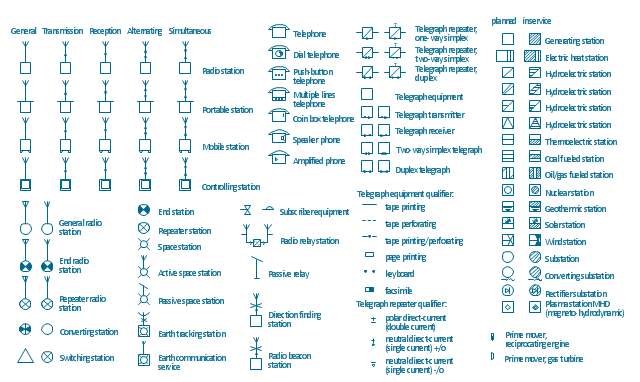
The vector stencils library "Stations" contains 110 symbols of communications equipment, generating, transmitting and receiving stations; substations; satellites; and power plants for power generation and distribution and radio relay systems.
"A power station (also referred to as a generating station, power plant, powerhouse or generating plant) is an industrial facility for the generation of electric power. At the center of nearly all power stations is a generator, a rotating machine that converts mechanical power into electrical power by creating relative motion between a magnetic field and a conductor. The energy source harnessed to turn the generator varies widely. It depends chiefly on which fuels are easily available, cheap enough and on the types of technology that the power company has access to. Most power stations in the world burn fossil fuels such as coal, oil, and natural gas to generate electricity, and some use nuclear power, but there is an increasing use of cleaner renewable sources such as solar, wind, wave and hydroelectric." [Power station. Wikipedia]
"Radio broadcasting is a one-way wireless transmission over radio waves intended to reach a wide audience. Stations can be linked in radio networks to broadcast a common radio format, either in broadcast syndication or simulcast or both. Audio broadcasting also can be done via cable radio, local wire television networks, satellite radio, and internet radio via streaming media on the Internet.
The signal types can be either analog audio or digital audio." [Radio broadcasting. Wikipedia]
The shapes example "Design elements - Stations" was drawn using the ConceptDraw PRO diagramming and vector drawing software extended with the Electrical Engineering solution from the Engineering area of ConceptDraw Solution Park.
Power and radio station symbols
Network Diagramming Software for Design Rack Diagrams
_Win_Mac.png "Network Diagramming Software, Design Elements — Network Layout (Windows, Macintosh)")
- Telecommunication Network Diagrams | Design elements ...
- Providing telecom services - Cross-functional flowchart | Telecom ...
- Network equipment and cabling layout - Template | Network layout ...
- Cisco Optical. Cisco icons, shapes, stencils and symbols | Cisco ...
- Process Flowchart | Basic Flowchart Symbols and Meaning | Flow ...
- Cable TV - Vector stencils library | Design elements - Cable TV ...
- Network Layout Floor Plans | Ethernet cable layout | Ethernet local ...
- Electrical Drawing Symbols Of Tv Cable
- ConceptDraw PRO Network Diagram Tool | Network Layout Floor ...
- Process Flowchart | Basic Flowchart Symbols and Meaning | How to ...
- Electrical Communication Symbols
- Odf Optic Fiber Network Diagram Symbol
- Cisco Optical. Cisco icons, shapes, stencils and symbols | Cisco ...
- Cable Symbols
- Symbol Of Tv In A Floor Plan
- Electrical Drawing Software and Electrical Symbols | Electrical ...
- Design elements - Cable TV (CATV) | Tree Network Topology ...
- Telephone Layout Floorplan
- Basic Flowchart Symbols and Meaning | Cisco Products Additional ...
- Cable TV - Vector stencils library