Android UI Design
 Android User Interface
The Android User Interface solution allows ConceptDraw DIAGRAM act as an Android UI design tool. Libraries and templates contain a variety of Android GUI elements to help users create images based on Android UI design.
Android User Interface

Android GUI
ERD Symbols and Meanings


 Windows 10 User Interface
Windows 10 User Interface solution extends significantly ConceptDraw DIAGRAM functionality with look-and-feel functions of GUI software and makes it a great assistant for Win10 designers, developers, and software engineers. This solution provides a wide s
 ConceptDraw Solution Park
ConceptDraw Solution Park collects graphic extensions, examples and learning materials
 iPhone User Interface
iPhone User Interface solution extends ConceptDraw DIAGRAM software with templates, samples and libraries with large quantity of vector stencils of graphical user interface elements, Apps icons, UI patterns for designing and prototyping of the iOS applic
Online Diagram Tool
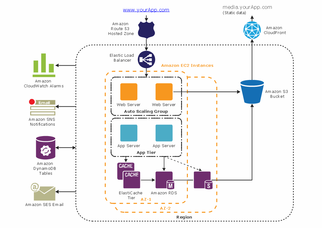
Diagramming tool - Amazon Web Services and Cloud Computing Diagrams
UML Block Diagram

UML Diagram

 Business Process Diagrams
Business Process Diagrams solution extends the ConceptDraw DIAGRAM BPM software with RapidDraw interface, templates, samples and numerous libraries based on the BPMN 1.2 and BPMN 2.0 standards, which give you the possibility to visualize equally easy simple and complex processes, to design business models, to quickly develop and document in details any business processes on the stages of project’s planning and implementation.
UML Flowchart Symbols

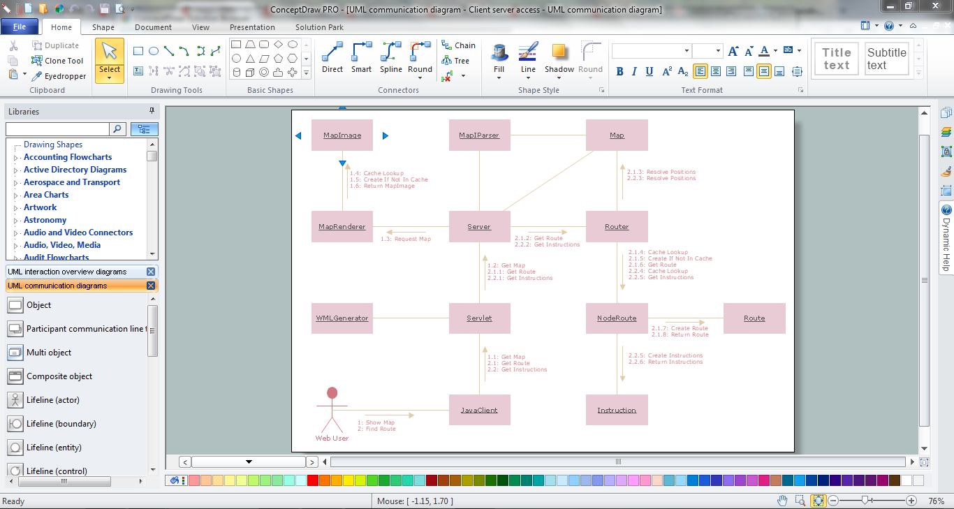
UML Collaboration Diagram (UML2.0)


- Android Notification Symbol List
- Design elements - Android system icons (action, alert) | Android 5.0 ...
- Android System Icons List
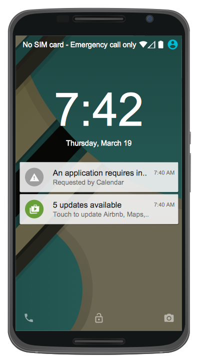
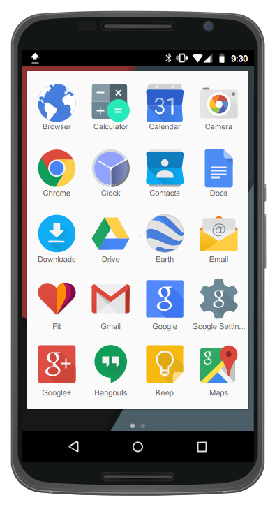
- Android 5.0 - Lock screen notifications | Android 5.0 - App drawer ...
- Android 5.0 - Gmail | Android 5.0 - App drawer | Android 5.0 - Lock ...
- Design elements - Android system icons ( notification ) | Design ...
- Android 5.0 - App drawer | Android 5.0 - Lock screen notifications ...
- Design elements - Android system icons ( notification ) | Design ...
- Notification Toggle Icons
- Gmail All Icon List
- Android 5.0 - List -style bottom sheet | Android 5.0 - Single-line list ...
- Design elements - Android system icons (device) | Android 5.0 - App ...
- Android 5.0 - Single-line list
- Design elements - Android system icons (communication) | Design ...
- Android 5.0 - App drawer | Design elements - Android UI | Android ...
- Android Interface Notification
- Entity Relationship Diagram Symbols | Android UI Design | ERD ...
- Android Smartphone Icon Png
- Android User Interface | Design elements - Android system icons ...
- Design elements - Android system icons ( notification ) | iPhone User ...