Electrical Symbols — Transformers and Windings

Electrical Symbols — Composite Assemblies

Electrical Symbols — Power Sources

Electrical Symbols — Semiconductor

Electrical Symbols — Qualifying

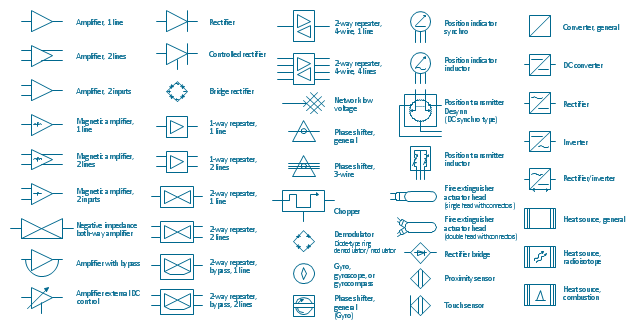
This vector stencils library contains 44 element symbols of transmitters (electronic amplifiers, repeaters), static devices (rectifiers), phase shift circuits, gyroscopes, and gyrators.
Use it to design the electronic circuit diagrams and electrical schematics.
"An electronic amplifier, amplifier, or (informally) amp is an electronic device that increases the power of a signal. It does this by taking energy from a power supply and controlling the output to match the input signal shape but with a larger amplitude. In this sense, an amplifier modulates the output of the power supply.
There are four basic types of electronic amplifier: the voltage amplifier, the current amplifier, the transconductance amplifier, and the transresistance amplifier. A further distinction is whether the output is a linear or exponential representation of the input. Amplifiers can also be categorized by their physical placement in the signal chain." [Amplifier. Wikipedia]
"A rectifier is an electrical device that converts Alternating Current (AC), which periodically reverses direction, to Direct Current (DC), which flows in only one direction. The process is known as rectification. Physically, rectifiers take a number of forms, including vacuum tube diodes, mercury-arc valves, copper and selenium oxide rectifiers, semiconductor diodes, silicon-controlled rectifiers and other silicon-based semiconductor switches." [Rectifier. Wikipedia]
"In telecommunications, a repeater is an electronic device that receives a signal and retransmits it at a higher level or higher power, or onto the other side of an obstruction, so that the signal can cover longer distances." [Repeater. Wikipedia]
"A phase shifter is a microwave network which provides a controllable phase shift of the RF signal. Phase shifters are used in phased arrays." [Phase shift module. Wikipedia]
"A vibrating structure gyroscope, standardised by IEEE as Coriolis vibratory gyroscope (CVG), is a wide group of gyroscope using solid-state resonators of different shapes that functions much like the halteres of an insect.
The underlying physical principle is that a vibrating object tends to continue vibrating in the same plane as its support rotates. In the engineering literature, this type of device is also known as a Coriolis vibratory gyro because as the plane of oscillation is rotated, the response detected by the transducer results from the Coriolis term in its equations of motion ("Coriolis force").
Vibrating structure gyroscopes are simpler and cheaper than conventional rotating gyroscopes of similar accuracy. Miniature devices using this principle are a relatively inexpensive type of attitude indicator." [Vibrating structure gyroscope. Wikipedia]
The example "Design elements - Composite assemblies" was drawn using the ConceptDraw PRO diagramming and vector drawing software extended with the Electrical Engineering solution from the Engineering area of ConceptDraw Solution Park.
Amplifiers, repeaters, rectifiers, phase shift circuits, gyroscopes, and gyrators
Electrical Symbols, Electrical Schematic Symbols

Electrical Symbols — VHF UHF SHF

- Electrical Symbols — Semiconductor | Electrical Symbols, Electrical ...
- Amplifier Circuit Schematics
- Electrical Symbols, Electrical Diagram Symbols | Circuits and Logic ...
- The Required Electronic Component And Symbols Of Audio Amp
- Symbol Amplifier Diagram
- Different Symbols Of Resistor
- Electrical Drawing Software and Electrical Symbols | Amplifier ...
- Design elements - Composite assemblies | Circuit diagram - EL 34 ...
- Different Kind Of Electrical Instrument And Their Symbols And Uses
- Symbol Meaning Of Diagram Lay Out Of Amplifier
- Network Amplifier Diagram
- Electrical Symbols — Logic Gate Diagram | Amplifier - Circuit ...
- Circuit Diagram Symbols For An Amplifier
- Stereo Amplifier Circut Diagram Com
- Different Symbols Of Electrical Components
- Electrical Symbols, Electrical Diagram Symbols | Electrical Symbols ...
- Symbols Of Electrical Wiring Of Audio Amplifier
- Amplifier Schematics
- Different Diodes And Their Symbol
- Schematic Diagram Of Different Types Of Valves