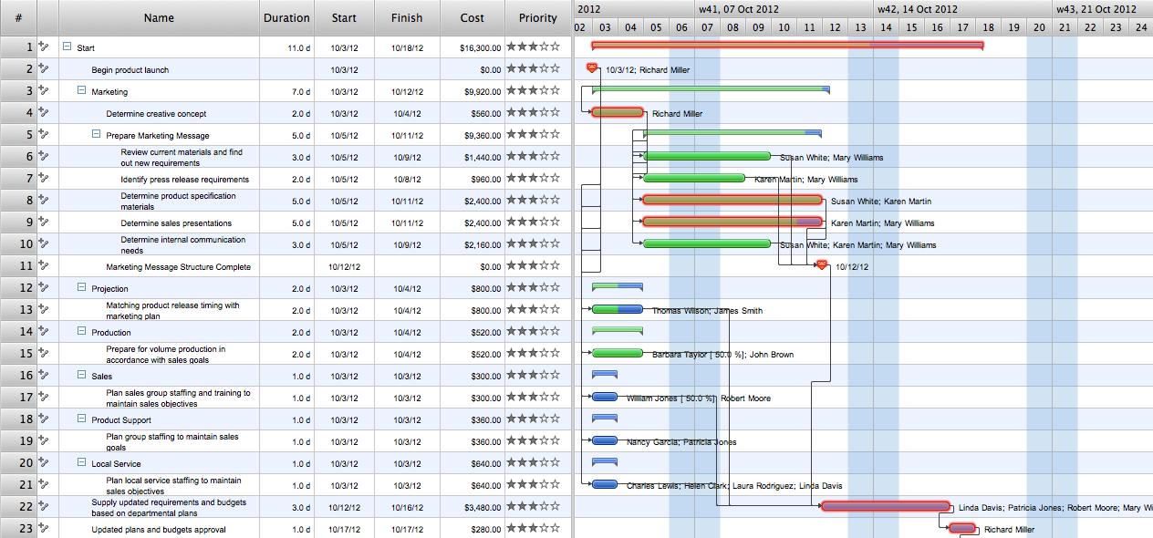
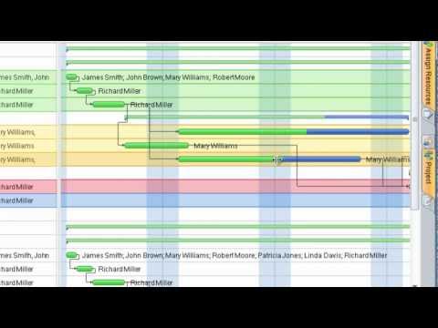
Gant Chart in Project Management
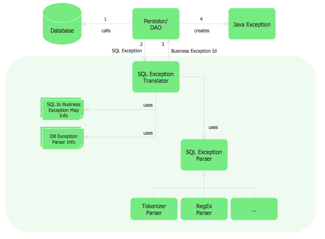
Sample Project Flowchart. Flowchart Examples

 Flowcharts
The Flowcharts solution for ConceptDraw DIAGRAM is a comprehensive set of examples and samples in several varied color themes for professionals that need to represent graphically a process. Solution value is added by the basic flow chart template and shapes' libraries of flowchart notation. ConceptDraw DIAGRAM flow chart creator lets one depict the processes of any complexity and length, as well as design the Flowchart either vertically or horizontally.
Flowchart Marketing Process. Flowchart Examples

UML Notation

- School Management Structure In A Flow Diagram
- Administration Management System Flowchart
- Warehouse with conveyor system - Floor plan | Lecture theatre ...
- 4 Level pyramid model diagram - Information systems types ...
- Process Flowchart | Basic Flowchart Symbols and Meaning | How to ...
- Warehouse with conveyor system - Floor plan | Warehouse layout ...
- Warehouse layout floor plan | Warehouse with conveyor system ...
- Sample Project Flowchart. Flowchart Examples | Flowchart ...
- Buble Diagram Of An Administration
- Plant Layout Plans | Emergency Plan | UML Class Diagram Tutorial ...
- Plant Layout Plans | Store Layout Software | Warehouse with ...
- Information Technology Architecture | Process Flowchart | Data Flow ...
- Euclidean algorithm - Flowchart | PROBLEM ANALYSIS. Identify and ...
- Arrangment Of Lan Pcs In A School Lab
- Plant Layout Plans | Emergency Plan | Store Layout Software ...
- Security and Access Plans | Security system plan | Design elements ...
- Hotel System Pic Flowchart
- How to Create a HR Process Flowchart Using ConceptDraw PRO ...
- Basic Flowchart Symbols and Meaning | Accounting Flowchart ...
- Defined The Information System And Diagrammatically Illustrate The