HelpDesk
How to Create a HVAC Plan
 HVAC Plans
Use HVAC Plans solution to create professional, clear and vivid HVAC-systems design plans, which represent effectively your HVAC marketing plan ideas, develop plans for modern ventilation units, central air heaters, to display the refrigeration systems for automated buildings control, environmental control, and energy systems.
This HVAC plan sample shows the air handler layout on the floor plan.
"An air handler, or air handling unit (often abbreviated to AHU), is a device used to condition and circulate air as part of a heating, ventilating, and air-conditioning (HVAC) system. An air handler is usually a large metal box containing a blower, heating or cooling elements, filter racks or chambers, sound attenuators, and dampers. Air handlers usually connect to a ductwork ventilation system that distributes the conditioned air through the building and returns it to the AHU. Sometimes AHUs discharge (supply) and admit (return) air directly to and from the space served without ductwork.
Small air handlers, for local use, are called terminal units, and may only include an air filter, coil, and blower; these simple terminal units are called blower coils or fan coil units. A larger air handler that conditions 100% outside air, and no recirculated air, is known as a makeup air unit (MAU). An air handler designed for outdoor use, typically on roofs, is known as a packaged unit (PU) or rooftop unit (RTU)." [Air handler. Wikipedia]
The floor plan example "Air handler - HVAC plan" was created using the ConceptDraw DIAGRAM diagramming and vector drawing software extended with the HVAC Plans solution from the Building Plans area of ConceptDraw Solution Park.
Floor plan

HVAC Marketing Plan
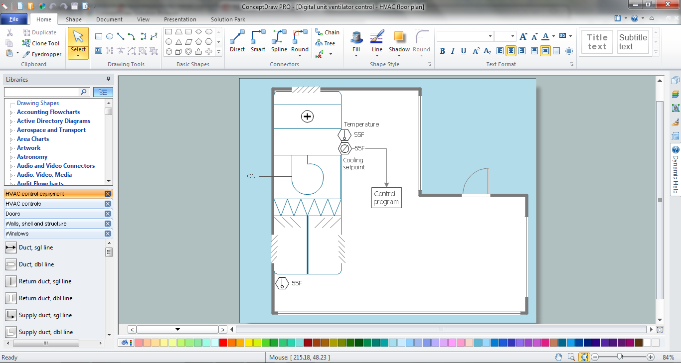
This HVAC floor plan sample illustrates the temperature sensors of air handler digital thermostat control.
"A thermostat is a component of a control system which senses the temperature of a system so that the system's temperature is maintained near a desired setpoint. The thermostat does this by switching heating or cooling devices on or off, or regulating the flow of a heat transfer fluid as needed, to maintain the correct temperature. The name is derived from the Greek words thermos "hot" and statos "a standing".
A thermostat may be a control unit for a heating or cooling system or a component part of a heater or air conditioner. Thermostats can be constructed in many ways and may use a variety of sensors to measure the temperature. The output of the sensor then controls the heating or cooling apparatus. A thermostat may switch on and off at temperatures either side of the setpoint the extent of the difference is known as hysteresis and prevents too frequent switching of the controlled equipment." [Thermostat. Wikipedia]
The HVAC plan example "Digital unit ventilator control" was created using the ConceptDraw DIAGRAM diagramming and vector drawing software extended with the HVAC Plans solution from the Building Plans area of ConceptDraw Solution Park.
HVAC floor plan

HVAC Business Plan
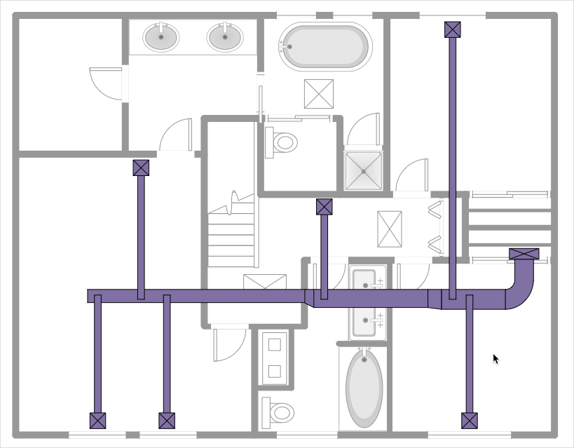
The vector stencil library "HVAC ductwork" contains 63 duct and vent symbols.
Use it for drawing HVAC system diagrams, heating, ventilation, air conditioning, refrigeration, automated building control, and environmental control design floor
plans and equipment layouts.
"Ducts are used in heating, ventilation, and air conditioning (HVAC) to deliver and remove air. These needed airflows include, for example, supply air, return air, and exhaust air. Ducts also deliver, most commonly as part of the supply air, ventilation air. As such, air ducts are one method of ensuring acceptable indoor air quality as well as thermal comfort.
A duct system is often called ductwork. Planning ('laying out'), sizing, optimizing, detailing, and finding the pressure losses through a duct system is called duct design." [Duct (HVAC). Wikipedia]
The vector stencils example "Design elements - HVAC ductwork" is included in HVAC Plans solution from the Building Plans area of ConceptDraw Solution Park.
HVAC ductwork symbols

The vector stencil library "HVAC equipment" contains 84 HVAC equipment symbols as pumps, fans, condensers, pipe coils, silencers, etc.
Use it for drawing HVAC system diagrams, heating, ventilation, air conditioning, refrigeration, automated building control, and environmental control design floor
plans and equipment layouts.
"HVAC (heating, ventilation, and air conditioning) is the technology of indoor and vehicular environmental comfort. HVAC system design is a subdiscipline of mechanical engineering, based on the principles of thermodynamics, fluid mechanics, and heat transfer. Refrigeration is sometimes added to the field's abbreviation as HVAC&R or HVACR, or ventilating is dropped as in HACR (such as the designation of HACR-rated circuit breakers).
HVAC is important in the design of medium to large industrial and office buildings such as skyscrapers and in marine environments such as aquariums, where safe and healthy building conditions are regulated with respect to temperature and humidity, using fresh air from outdoors." [HVAC. Wikipedia]
The vector stencils example "Design elements - HVAC equipment" is included in HVAC Plans solution from the Building Plans area of ConceptDraw Solution Park.
HVAC equipment symbols

The vector stencil library "HVAC controls" contains contains 24 HVAC control symbols: sensors, actuators, timers, controllers, I/ O points.
Use it for drawing HVAC system diagrams, heating, ventilation, air conditioning, refrigeration, automated building control, and environmental control design floor
plans and equipment layouts.
"HVAC (... Heating, Ventilation and Air Conditioning) is a control system that applies regulation to a heating and/ or air conditioning system. ...
Central controllers and most terminal unit controllers are programmable, meaning the direct digital control program code may be customized for the intended use. The program features include time schedules, setpoints, controllers, logic, timers, trend logs, and alarms. The unit controllers typically have analog and digital inputs that allow measurement of the variable (temperature, humidity, or pressure) and analog and digital outputs for control of the transport medium (hot/ cold water and/ or steam). Digital inputs are typically (dry) contacts from a control device, and analog inputs are typically a voltage or current measurement from a variable (temperature, humidity, velocity, or pressure) sensing device. Digital outputs are typically relay contacts used to start and stop equipment, and analog outputs are typically voltage or current signals to control the movement of the medium (air/ water/ steam) control devices such as valves, dampers, and motors." [HVAC control system. Wikipedia]
The vector stencils example "Design elements - HVAC controls" is included in HVAC Plans solution from the Building Plans area of ConceptDraw Solution
Park.
HVAC control symbols

The vector stencils library "HVAC equipment" contains 26 symbols of HVAC equipment. Use it for drawing HVAC system diagrams, heating, ventilation, air conditioning, refrigeration, automated building control and environmental control system layout floor plans in the ConceptDraw PRO diagramming and vector drawing software extended with the HVAC Plans solution from the Building Plans area of ConceptDraw Solution Park.
Rotary pump

Pump

Centrifugal pump

Fan blades, hor.

Fan blades, vert.

Fan blades, 4

Reciprocating pump

Screw pump

Centrifugal fan

Centrifugal fan 2

Axial fan

Axial fan 2

Moisture eliminator

Condenser

Condenser, plate type

Condenser, coil type

Air filter

Dryer

Silencer

Silencer 2

Pipe coil

Pipe coil, fins

Pipe coil, plate

Pipe coil, plate, fins

Refrigerant receiver

Chiller

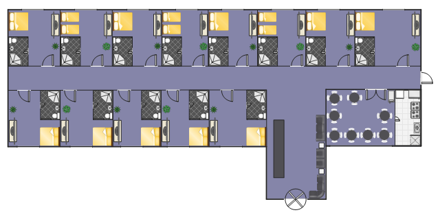
This example depicts furniture and home appliances layout on the hotel floor plan.
"A hotel is an establishment that provides lodging paid on a short-term basis. The provision of basic accommodation, in times past, consisting only of a room with a bed, a cupboard, a small table and a washstand has largely been replaced by rooms with modern facilities, including en-suite bathrooms and air conditioning or climate control. Additional common features found in hotel rooms are a telephone, an alarm clock, a television, a safe, a mini-bar with snack foods and drinks, and facilities for making tea and coffee. Luxury features include bathrobes and slippers, a pillow menu, twin-sink vanities, and jacuzzi bathtubs. Larger hotels may provide additional guest facilities such as a swimming pool, fitness center, business center, childcare, conference facilities and social function services." [Hotel. Wikipedia]
The example "Hotel floor plan" was created using the ConceptDraw PRO diagramming and vector drawing software extended with the Floor Plans solution from the Building Plans area of ConceptDraw Solution Park.
Floor plan
Interior Design. Registers, Drills and Diffusers — Design Elements

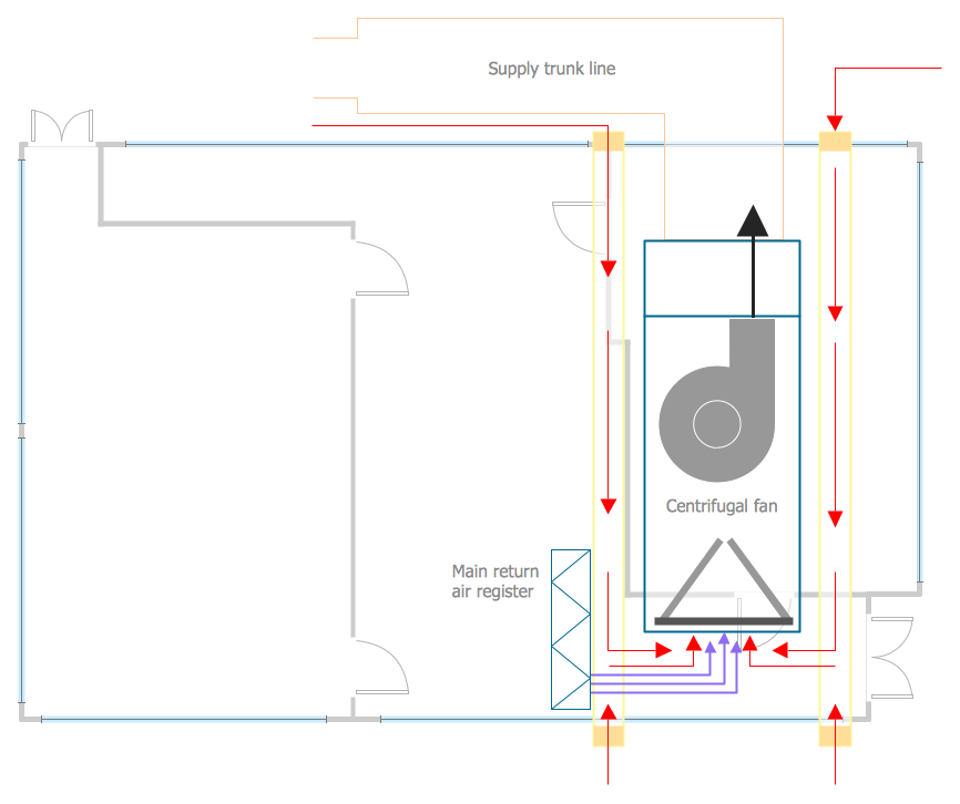
This mechanical room HVAC plan sample shows the layout of air handler (air handling unit, AHU) equipment: mixing chamber, air filter, fan (blower), heat exchanger coil, diffusers.
"Ventilating (the V in HVAC) is the process of "changing" or replacing air in any space to provide high indoor air quality (i.e. to control temperature, replenish oxygen, or remove moisture, odors, smoke, heat, dust, airborne bacteria, and carbon dioxide). Ventilation is used to remove unpleasant smells and excessive moisture, introduce outside air, to keep interior building air circulating, and to prevent stagnation of the interior air.
Ventilation includes both the exchange of air to the outside as well as circulation of air within the building. It is one of the most important factors for maintaining acceptable indoor air quality in buildings. Methods for ventilating a building may be divided into mechanical/ forced and natural types.
"Mechanical" or "forced" ventilation is used to control indoor air quality. Excess humidity, odors, and contaminants can often be controlled via dilution or replacement with outside air. However, in humid climates much energy is required to remove excess moisture from ventilation air.
Ventilation increases the energy needed for heating or cooling, however heat recovery ventilation can be used to mitigate the energy consumption. This involves heat exchange between incoming and outgoing air. Energy recovery ventilation additionally includes exchange of humidity." [Ventilation (architecture). Wikipedia]
The HVAC floor plan example "Ventilation system layout" was created using the ConceptDraw DIAGRAM diagramming and vector drawing software extended with the HVAC Plans solution from the Building Plans area of ConceptDraw Solution Park.
HVAC floor plan

 Cafe and Restaurant Floor Plans
Restaurants and cafes are popular places for recreation, relaxation, and are the scene for many impressions and memories, so their construction and design requires special attention. Restaurants must to be projected and constructed to be comfortable and e
- HVAC Plans | Air handler- HVAC plan | How to Create a HVAC Plan ...
- HVAC Plans | Block diagram - Automotive HVAC system | Design ...
- Minihotel floor plan | Air handler- HVAC plan | Doors - Vector ...
- Hvac Floorplans
- HVAC Plans | ConceptDraw Solution Park | Collaboration Area ...
- How to Create a HVAC Plan | Cafe and Restaurant Floor Plan ...
- Room planning with ConceptDraw PRO | Floor Plans | Home floor ...
- Building Plans with ConceptDraw PRO | Floor Plans | Room ...
- Hvac Floor Plans
- How to Create a HVAC Plan | Building Drawing Software for Design ...
- Package Air Conditioner Symbol In Floor Plan
- Room planning with ConceptDraw PRO | Floor Plans | How To Make ...
- Floor Plans | Home floor plan template | Room planning with ...
- How to Create a HVAC Plan | Interior Design Registers, Drills and ...
- Security system floor plan | Air handler- HVAC plan | Office wireless ...
- Security system floor plan | Design elements - HVAC controls ...
- Home floor plan template | Room planning with ConceptDraw PRO ...
- HVAC Plans | Design elements - HVAC control equipment | Design ...
- Cafe electrical floor plan | Engineering | Design elements ...
- Network layout floorplan - Vector stencils library | Home floor plan ...