The vector stencils library "UML activity diagrams" contains 37 symbols for the ConceptDraw PRO diagramming and vector drawing software.
"Activity diagrams are constructed from a limited number of shapes, connected with arrows. The most important shape types:
(1) rounded rectangles represent actions;
(2) diamonds represent decisions;
(3) bars represent the start (split) or end (join) of concurrent activities;
(4) a black circle represents the start (initial state) of the workflow;
(5) an encircled black circle represents the end (final state).
Arrows run from the start towards the end and represent the order in which activities happen.
Hence they can be regarded as a form of flowchart. Typical flowchart techniques lack constructs for expressing concurrency. However, the join and split symbols in activity diagrams only resolve this for simple cases; the meaning of the model is not clear when they are arbitrarily combined with decisions or loops." [Activity diagram. Wikipedia]
The example "Design elements - UML activity diagrams" is included in the Rapid UML solution from the Software Development area of ConceptDraw Solution Park.
UML activity diagram symbols

The vector stencils library "Bank UML activity diagram" contains 32 shapes of UML activity diagram.
Use it for object-oriented modeling of your bank information system.
"Activity diagrams are constructed from a limited number of shapes, connected with arrows. The most important shape types:
* rounded rectangles represent actions;
* diamonds represent decisions;
* bars represent the start (split) or end (join) of concurrent activities;
* a black circle represents the start (initial state) of the workflow;
* an encircled black circle represents the end (final state).
Arrows run from the start towards the end and represent the order in which activities happen.
Activity diagrams may be regarded as a form of flowchart. Typical flowchart techniques lack constructs for expressing concurrency. However, the join and split symbols in activity diagrams only resolve this for simple cases; the meaning of the model is not clear when they are arbitrarily combined with decisions or loops.
While in UML 1.x, activity diagrams were a specialized form of state diagrams, in UML 2.x, the activity diagrams were reformalized to be based on Petri net-like semantics, increasing the scope of situations that can be modeled using activity diagrams. These changes cause many UML 1.x activity diagrams to be interpreted differently in UML 2.x." [Activity diagram. Wikipedia]
This example of UML activity diagram symbols for the ConceptDraw PRO diagramming and vector drawing software is included in the ATM UML Diagrams solution from the Software Development area of ConceptDraw Solution Park.
UML activity diagram symbols

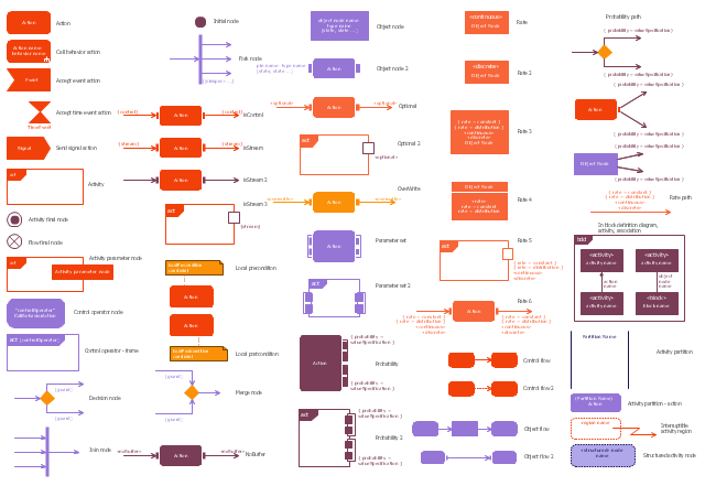
This vector stencils library contains 47 SysML activity diagram symbols.
Use it to design your SysML activity diagrams using ConceptDraw PRO diagramming and vector drawing software.
"Activity diagrams are constructed from a limited number of shapes, connected with arrows. The most important shape types:
- rounded rectangles represent actions;
- diamonds represent decisions;
- bars represent the start (split) or end (join) of concurrent activities;
- a black circle represents the start (initial state) of the workflow;
- an encircled black circle represents the end (final state).
Arrows run from the start towards the end and represent the order in which activities happen." [Activity diagram. Wikipedia]
The vector stencils library "Activity diagram" is included in the SysML solution from the Software Development area of ConceptDraw Solution Park.
Action

Call behavior action

Accept event action

Accept time event action

Send signal action

Activity

Activity final node

Flow final node

Activity parameter node

Control operator node

Control operator - frame

Decision/Merge node

Fork/Join node

Initial node

isControl

isStream

isStream 2

isStream 3

Local precondition

Local postcondition

NoBuffer

Object node

Object node 2

Optional

Optional 2

OverWrite

Parameter set

Parameter set 2

Probability

Probability 2

Rate

Rate 2

Rate 3

Rate 4

Rate 5

Rate 6

Control flow

Control flow 2

Object flow

Object flow 2

Probability path

Rate path

In block definition diagram, activity, association

Activity partition

Activity partition - action

Interruptible activity region

Structured activity node

UML Activity Diagram. Design Elements
")

UML Activity Diagram

The vector stencils library "Activity diagram" contains 47 symbols.
Use it to design your SysML activity diagrams using ConceptDraw PRO diagramming and vector drawing software.
"Activity diagrams are constructed from a limited number of shapes, connected with arrows. The most important shape types:
- rounded rectangles represent actions;
- diamonds represent decisions;
- bars represent the start (split) or end (join) of concurrent activities;
- a black circle represents the start (initial state) of the workflow;
- an encircled black circle represents the end (final state).
Arrows run from the start towards the end and represent the order in which activities happen." [Activity diagram. Wikipedia]
The SysML shapes example "Design elements - Activity diagram" is included in the SysML solution from the Software Development area of ConceptDraw Solution Park.
SysML activity diagram symbols
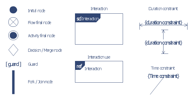
The vector stencils library "Bank UML interaction overview diagram" contains 11 shapes for drawing UML interaction overview diagrams.
Use it for object-oriented modeling of your bank information system.
"The interaction overview diagram is similar to the activity diagram, in that both visualize a sequence of activities. The difference is that, for an interaction overview, each individual activity is pictured as a frame which can contain a nested interaction diagrams. ...
The other notation elements for interaction overview diagrams are the same as for activity diagrams. These include initial, final, decision, merge, fork and join nodes. The two new elements in the interaction overview diagrams are the "interaction occurrences" and "interaction elements"." [Interaction overview diagram. Wikipedia]
This example of UML interaction overview diagram symbols for the ConceptDraw PRO diagramming and vector drawing software is included in the ATM UML Diagrams solution from the Software Development area of ConceptDraw Solution Park.
UML interaction overview diagram symbols
Basic Flowchart Symbols and Meaning


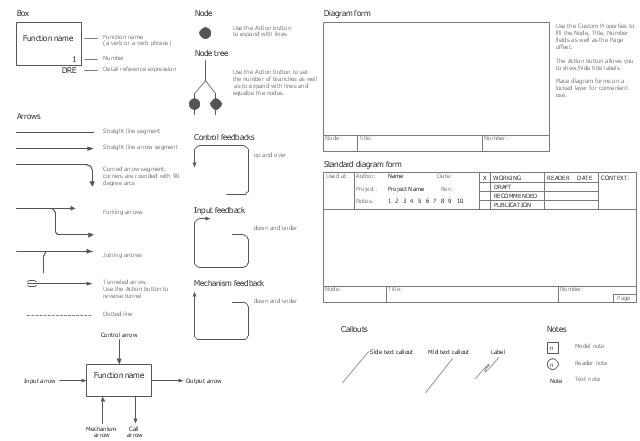
The vector stencils library "IDEF0" contains 26 IDEF0 diagram symbols.
Use it for business process modeling with IDEF0 diagrams.
"The IDEF0 model ... is based on a simple syntax. Each activity is described by a verb-based label placed in a box. Inputs are shown as arrows entering the left side of the activity box while output are shown as exiting arrows on the right side of the box. Controls are displayed as arrows entering the top of the box and mechanisms are displayed as arrows entering from the bottom of the box. Inputs, Controls, Outputs, and Mechanisms are all referred to as concepts.
- Arrow: A directed line, composed of one or more arrow segments, that models an open channel or conduit conveying data or objects from source (no arrowhead) to use (with arrowhead). There are 4 arrow classes: Input Arrow, Output Arrow, Control Arrow, and Mechanism Arrow (includes Call Arrow). See Arrow Segment, Boundary Arrow, Internal Arrow.
- Box: A rectangle, containing a name and number, used to represent a function.
- Context: The immediate environment in which a function (or set of functions on a diagram) operates.
- Decomposition: The partitioning of a modeled function into its component functions.
- Fork: The junction at which an IDEF0 arrow segment (going from source to use) divides into two or more arrow segments. May denote unbundling of meaning.
- Function: An activity, process, or transformation (modeled by an IDEF0 box) identified by a verb or verb phrase that describes what must be accomplished.
- Join: The junction at which an IDEF0 arrow segment (going from source to use) merges with one or more other arrow segments to form a single arrow segment. May denote bundling of arrow segment meanings.
- Node: A box from which child boxes originate; a parent box. See Node Index, Node Tree, Node Number, Node Reference, Diagram Node Number." [IDEF0. Wikipedia]
The shapes example "Design elements - IDEF0" was created using the ConceptDraw PRO diagramming and vector drawing software extended with the solution "IDEF Business Process Diagrams" from the area "Business Processes" of ConceptDraw Solution Park.
IDEF0 diagram symbols
- Diagramming Software for Design UML Activity Diagrams | UML ...
- Design elements - UML activity diagrams
- Design elements - Bank UML activity diagram | Vector stencils ...
- Design elements - UML activity diagrams | Design elements - Bank ...
- Activity Diagram Symbols Swimlanes
- Design elements - Bank UML activity diagram | Process Flowchart ...
- UML Activity Diagram
- Process Flowchart | Design elements - UML activity diagrams ...
- UML activity diagram (swimlanes) - Template
- Swim Lane Flowchart Symbols | Design elements - UML activity ...
- UML Activity Diagram . Design Elements | Design elements - UML ...
- Uml Activity Diagram Symbols
- UML activity diagram (swimlanes) - Template | Swim Lane Flowchart ...
- UML activity diagram (swimlanes) - Template | Design elements ...
- Swim Lane Flowchart Symbols | UML activity diagram (swimlanes ...
- UML activity diagram - Cash withdrawal from ATM | Design elements ...
- Design elements - Bank UML activity diagram | Swim Lane ...
- UML Activity Diagram | Diagramming Software for Design UML ...
- Design elements - Bank UML activity diagram | Business Process ...
- Design elements - UML activity diagrams | Cross-Functional ...