The vector stencils library "Rack diagrams" contains 55 hardware symbols for creating the server rack layout diagrams using the ConceptDraw PRO diagramming and vector drawing software.
"A 19-inch rack is a standardized frame or enclosure for mounting multiple equipment modules. Each module has a front panel that is 19 inches wide, including edges or ears that protrude on each side which allow the module to be fastened to the rack frame with screws. Equipment designed to be placed in a rack is typically described as rack-mount, rack-mount instrument, a rack mounted system, a rack mount chassis, subrack, rack mountable, or occasionally simply shelf. The industry standard rack cabinet is 42U tall." [19-inch rack. Wikipedia]
"A rack unit, U or RU is a unit of measure that describes the height of equipment designed to mount in a 19-inch rack or a 23-inch rack. The size of a piece of rack-mounted equipment is frequently described as a number in "U". For example, one rack unit is often referred to as "1U", 2 rack units as "2U" and so on.
A typical full size rack is 42U, which means it holds just over 6 feet of equipment, and a typical "half-height" rack would be 18-22U, or around 3 feet high." [Rack unit. Wikipedia]
The example "Design elements - Rack diagram" is included in the Rack Diagrams solution from the Computer and Networks area of ConceptDraw Solution Park.
Rack diagram elements
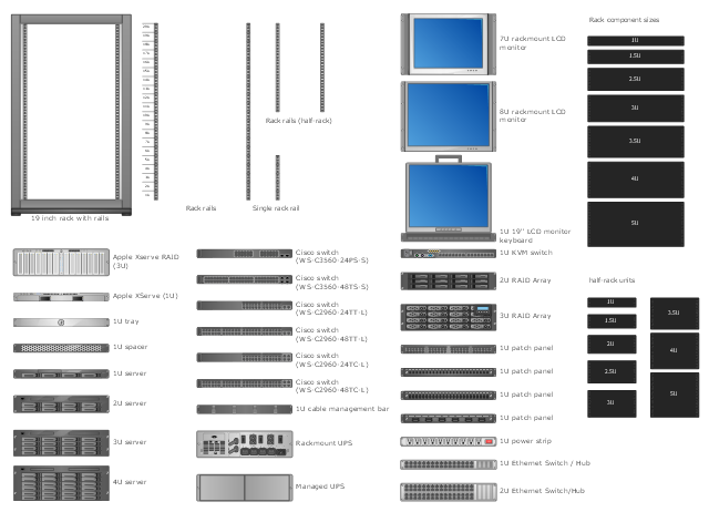
Server rack diagrams visualize the the rack mounting of computer and network equipment as the drawing of frontal view of the rack with equipment installed. They are used for choosing the equipment or racks to buy, and help to organize equipment on the racks virtually, without the real installation.
"A 19-inch rack is a standardized frame or enclosure for mounting multiple equipment modules. Each module has a front panel that is 19 inches (482.6 mm) wide, including edges or ears that protrude on each side which allow the module to be fastened to the rack frame with screws." [19-inch rack. Wikipedia]
"A rack unit, U or RU is a unit of measure that describes the height of equipment designed to mount in a 19-inch rack or a 23-inch rack. The 19-inch (482.6 mm) or 23-inch (584.2 mm) dimension refers to the width of the equipment mounting frame in the rack including the frame; the width of the equipment that can be mounted inside the rack is less. One rack unit is 1.75 inches (4.445 cm) high.
The size of a piece of rack-mounted equipment is frequently described as a number in "U". For example, one rack unit is often referred to as "1U", 2 rack units as "2U" and so on.
A typical full size rack is 42U, which means it holds just over 6 feet of equipment, and a typical "half-height" rack would be 18-22U, or around 3 feet high." [Rack unit. Wikipedia]
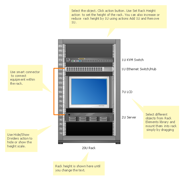
The rack diagram template is included in the Rack Diagrams solution from the Computer and Networks area of ConceptDraw Solution Park.
"A 19-inch rack is a standardized frame or enclosure for mounting multiple equipment modules. Each module has a front panel that is 19 inches (482.6 mm) wide, including edges or ears that protrude on each side which allow the module to be fastened to the rack frame with screws." [19-inch rack. Wikipedia]
"A rack unit, U or RU is a unit of measure that describes the height of equipment designed to mount in a 19-inch rack or a 23-inch rack. The 19-inch (482.6 mm) or 23-inch (584.2 mm) dimension refers to the width of the equipment mounting frame in the rack including the frame; the width of the equipment that can be mounted inside the rack is less. One rack unit is 1.75 inches (4.445 cm) high.
The size of a piece of rack-mounted equipment is frequently described as a number in "U". For example, one rack unit is often referred to as "1U", 2 rack units as "2U" and so on.
A typical full size rack is 42U, which means it holds just over 6 feet of equipment, and a typical "half-height" rack would be 18-22U, or around 3 feet high." [Rack unit. Wikipedia]
The rack diagram template is included in the Rack Diagrams solution from the Computer and Networks area of ConceptDraw Solution Park.
Rack diagram template
Electrical Symbols — Switches and Relays

Electrical Symbols, Electrical Diagram Symbols

How To use House Electrical Plan Software


SWOT Template

Security Plans

- 42u Rack Means
- 42u Rack Network Equipment
- Rack diagram - Template | 42u Rack Dimensions Wiki
- How Tall Is 42u Rack
- 42u Rack Stencil
- Detailed Diagram Of A 42u Rack
- Rack Diagrams | How to Create a Rack Diagram in ConceptDraw ...
- Rack units | Rack Diagrams | Design elements - Rack diagram ...
- Rack diagram - Template | How To use Switches in Network ...
- Design elements - Rack diagram | Measurement Of 1u Rack Cabinets