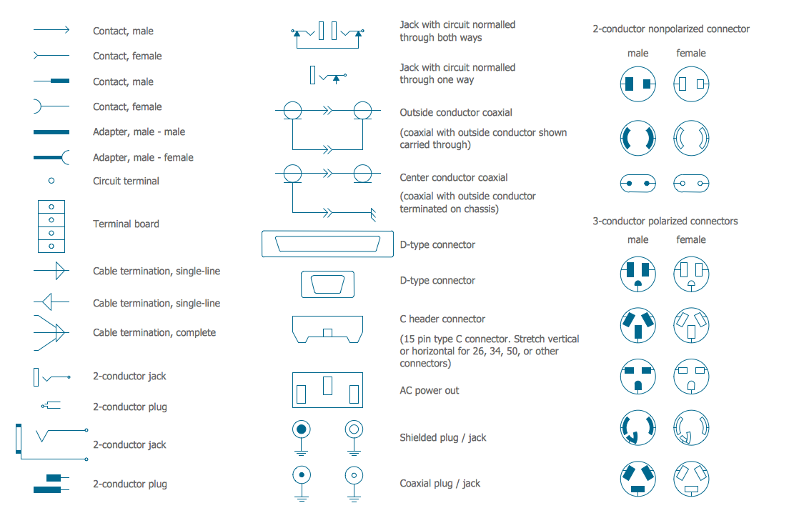
Electrical Symbols — Terminals and Connectors
Network wiring cable. Computer and Network Examples


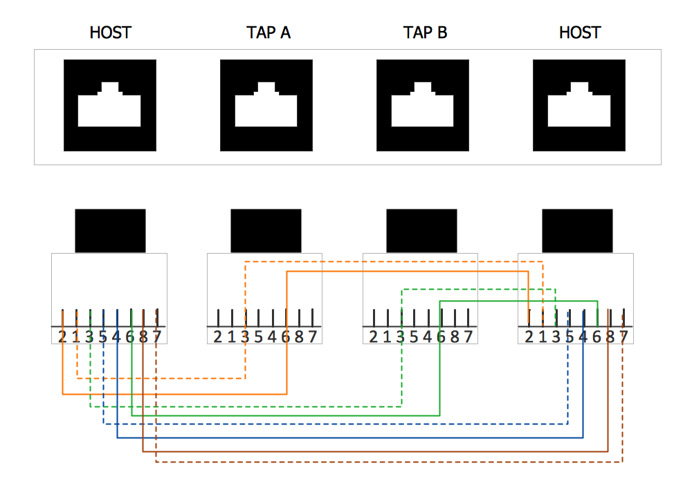
Local area network (LAN). Computer and Network Examples

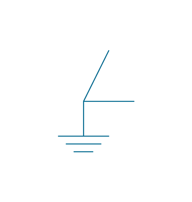
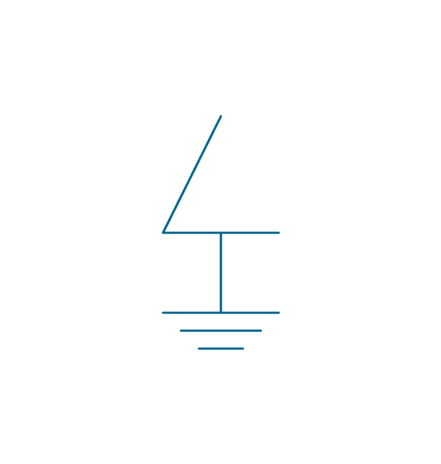
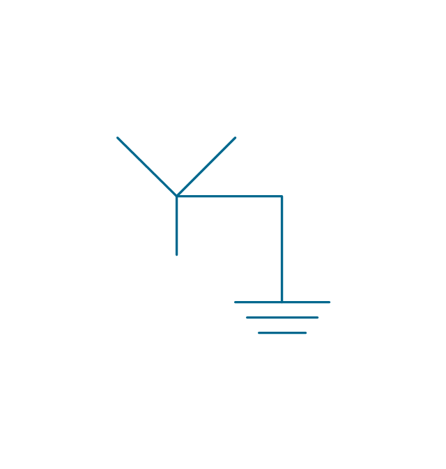
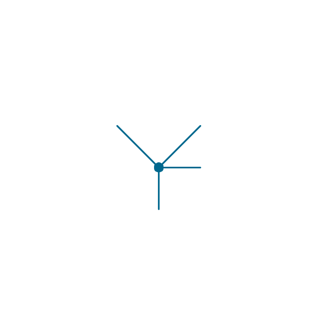
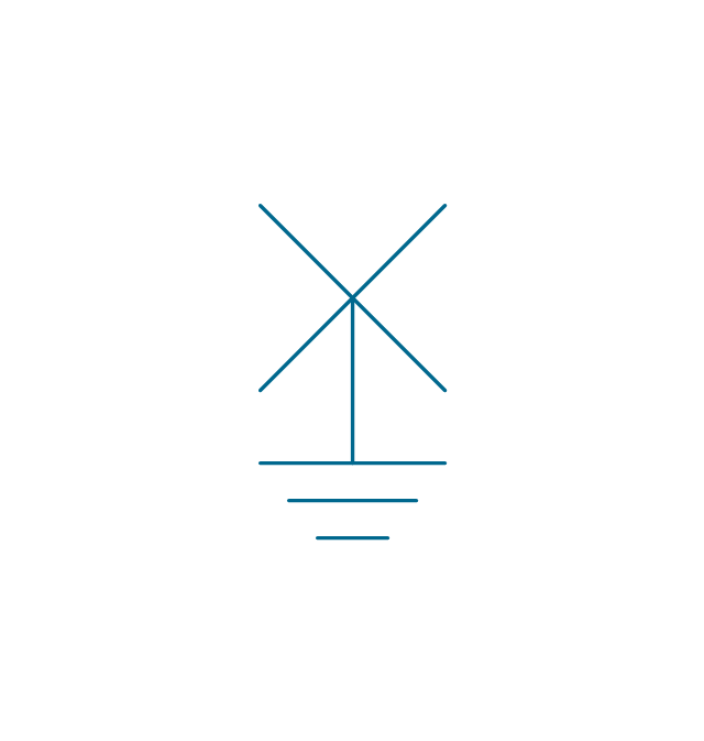
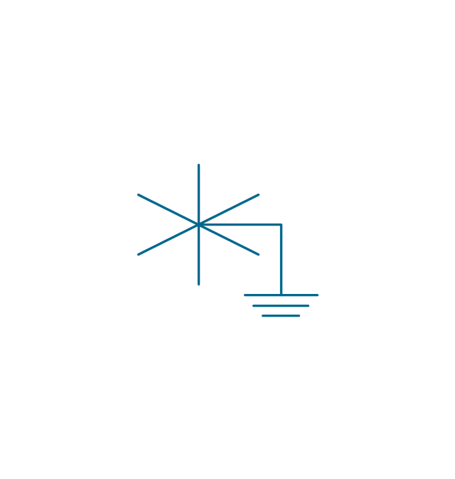
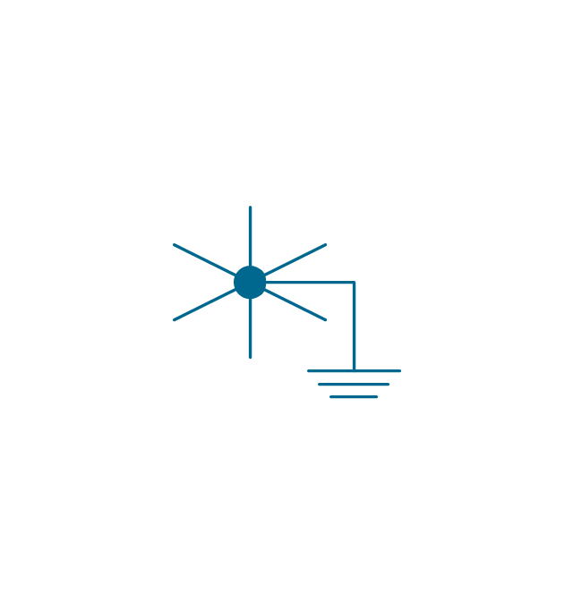
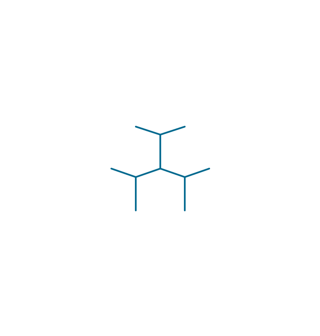
The vector stencils library "Qualifying" contains 56 qualifying symbols.
Use these shapes to annotate or specify characteristics of objects in electrical drawings, electronic schematics, circuit diagrams, electromechanical drawings, and wiring diagrams, cabling layout diagrams in the ConceptDraw PRO diagramming and vector drawing software extended with the Electrical Engineering solution from the Engineering area of ConceptDraw Solution Park.
www.conceptdraw.com/ solution-park/ engineering-electrical
Positive polarity

Negative polarity

Neutral symbol

6-phase double delta

Electret

Radiation, non-ion.
Radiation, ion.
Radiation, non-ion., coherent
Radiation, ion., coherent
Radiation, non-ion. 2
Radiation, ion. 2
Radiation, non-ion., coherent 2
Radiation, ion., coherent 2
Multiple-phase

Multiple-phase 2

Multiple-phase, interconnect.

Multiple-phase, interconnect. 2

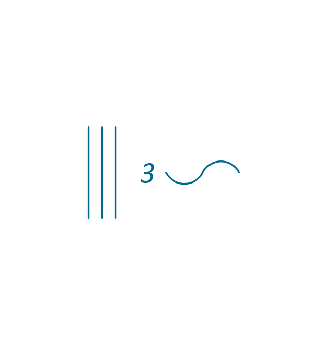
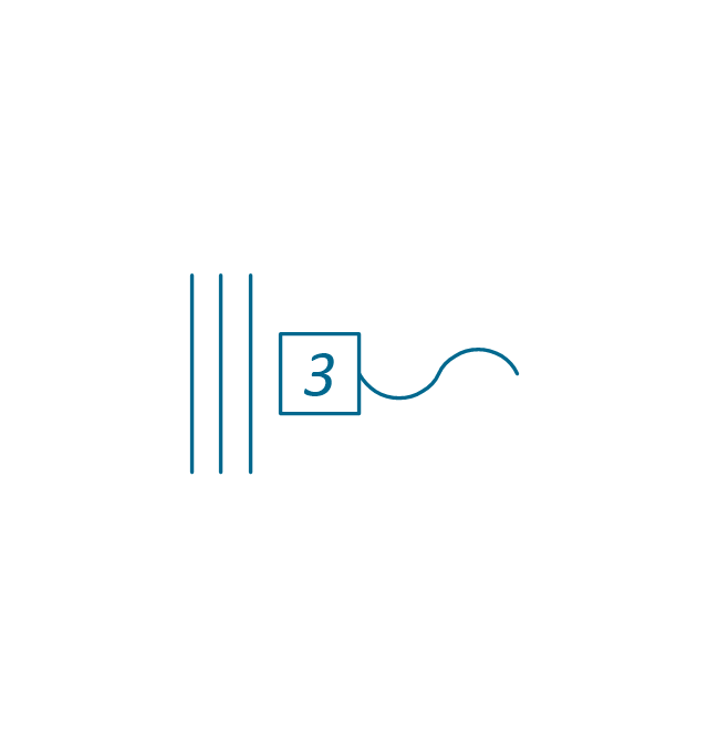
3 separate windings

3 separate windings, interconnect.
3 separate windings, interconnect. 2
3-phase (V)
-qualifying---vector-stencils-library.png--diagram-flowchart-example.png)
3-Phase (T)
-qualifying---vector-stencils-library.png--diagram-flowchart-example.png)
3-phase delta 3

3-phase delta 1

3-phase delta 1, grounded
3-phase delta 2

3-phase delta 2, grounded
3-phase delta 2, grounded 2
3-phase delta 4

3-phase delta 4, grounded

3-phase star, general

3-phase star, grounded
3-phase star, neutral brought out
3-phase zigzag

3-phase zigzag, grounded
3-phase 4-wire, general

3-phase 4-wire, grounded
3-phase 4-wire, neutral brought out

2-phase 3-wire

2-phase 3-wire, separated

2-phase 3-wire, grounded

2-phase 3-wire, separat., ground.
2-phase 4-wire

2-phase 4-wire, grounded
4-phase, general

4-phase, grounded
4-phase, neutral brought out

6-phase double star

6-phase double star, grounded
6-phase double star 2

6-phase double star, grounded 2
6-phase polygon

6-phase fork
6-phase fork, neutral

Special connector

Coaxial symbol

Electrical Symbols, Electrical Diagram Symbols

Electrical Symbols — Transmission Paths
The vector stencils library "Terminals and connectors" contains 43 element symbols of terminals, connectors, plugs, polarized connectors, jacks, coaxial cables, and conductors.
Use it for drawing the wiring diagrams, electrical layouts, electronic schematics, and circuit diagrams in the ConceptDraw PRO diagramming and vector drawing software extended with the Electrical Engineering solution from the Engineering area of ConceptDraw Solution Park.
www.conceptdraw.com/ solution-park/ engineering-electrical
2-conductor jack

2-conductor plug

2-conductor jack 2

2-conductor plug 2

Normalled jacks

Normalled jack

Outside conductor coaxial

Center conductor coaxial

Large D connector

Small D connector

C header connector

Normalled jacks

Сontact, male

Сontact, female

Сontact, male 2

Сontact, female 2

Adapter, male - male

Adapter, male - male

Circuit terminal

Terminal board

Cable termination, complete

Cable termination, single-line

Cable termination, single-line 2

Shielded jack

Shielded plug

Coaxial jack

Coaxial plug

2-conductor, male

2-conductor, female

2-conductor, male 2

2-conductor, female 2

2-conductor, male 3

2-conductor, female 3

3-conductor, male

3-conductor, female

3-conductor, male 2

3-conductor, female 2

3-conductor, male 3

3-conductor, female 3

3-conductor, male 4

3-conductor, female 4

3-conductor, male 5

3-conductor, female 5

The vector stencils library "Cable TV" contains 64 symbols of cable TV network equipment.
Use these shapes for drawing CATV system design floor plans, network topology diagrams, wiring diagrams and cabling layout schemes in the ConceptDraw PRO diagramming and vector drawing software.
The vector stencils library "Cable TV" is included in the Electric and Telecom Plans solution from the Building Plans area of ConceptDraw Solution Park.
Output Directional Tap 1

Output Directional Tap 2

Output Directional Tap 3

Output Directional Tap 4

Output Directional Tap 5

2-way Splitter

3-way Splitter

4-way Splitter

AC Power Block

Bond

Down Guy

Building Guy and Anchor

Rock Guy with Anchor

Down Guy with Anchor

Pole-to-Pole Guy

Sidewalk Down Guy with Anchor

Sidewalk Down Guy

Slack Span Messenger Wire

Tensioned Messenger Wire w/out cable

Tensioned Messenger Wire

Ground

Joint Usage (Power & Telephone Pole)
-cable-tv---vector-stencils-library.png--diagram-flowchart-example.png)
Joint Usgae Pole with Transformer

Strut

Tree Guy with Anchor

Push Brace (smaller pole in actual relative position)
-cable-tv---vector-stencils-library.png--diagram-flowchart-example.png)
Extension Arm

Built CATV Pole

Proposed CATV Pole

Directional Tap 1

Directional Tap 2

Manhole

Telephone Pole

Riser Pole

Vault Handheld

Fixed Equalizer

Fixed Flat Attenuators

Other Supporting Structures

Pedestal - Underground Routing

Power Pole

Direct Buried Underground Routing

Duct Line Underground Routing

Line Terminations

2-Way Optical Splice Location

3-Way Optical Splice Location

4-Way Optical Splice Location

> 4-Way Optical Splice Location

Optical Amplifier

Cable AC Power Combiner

Optical Fiber Cable

Optical Connector

Wavelength Demultiplexer

Wavelength Multiplexer

Optical Transmitter

Optical Transmitter

Optical Node

Optical Splitter

Headend (Signal Processing)
-cable-tv---vector-stencils-library.png--diagram-flowchart-example.png)
Node

Primary Hub

Secondary Hub

Coaxial Splice

Power Supply

Variable Equalizer

Network wiring. Computer and Network Examples
Network Topologies


- Design elements - Terminals and connectors | Cable TV - Vector ...
- Network wiring cable . Computer and Network Examples | Basic ...
- Network Cable Layout Plan
- Electrical Symbols — Terminals and Connectors | Cable TV - Vector ...
- Symbol For Coax Cable
- Wire To Wire Conection Symbol
- Design elements - Terminals and connectors | Design elements ...
- Cable Tv Symbols
- Electrical Symbols — Qualifying | Qualifying - Vector stencils library ...
- Optical Fiber Connection Line Diagram Tools