UML Class Diagram Tutorial
The Rapid UML Solution from the Software Development area of ConceptDraw Solution Park helps you to create the UML Class Diagrams quick and easy using ConceptDraw PRO diagramming and vector drawing software.Diagramming Software for Design UML Interaction Overview Diagrams
UML Interaction Overview Diagram schematically shows a control flow with nodes and a sequence of activities that can contain interaction or sequence diagrams.
 Crystal Mapping
With Crystal Mapping all goals and relevant information can be observed in one radiant dashboard.
 Fishbone Diagram
Fishbone Diagrams solution extends ConceptDraw PRO software with templates, samples and library of vector stencils for drawing the Ishikawa diagrams for cause and effect analysis.
 Entity-Relationship Diagram (ERD)
Entity-Relationship Diagram (ERD) solution extends ConceptDraw PRO software with templates, samples and libraries of vector stencils from drawing the ER-diagrams by Chen's and crow’s foot notations.
 Event-driven Process Chain Diagrams
Event-driven Process Chain (EPC) Diagram is a type of flowchart widely used for modeling in business engineering and reengineering, business process improvement, and analysis. EPC method was developed within the Architecture of Integrated Information Systems (ARIS) framework.
 Interactive Voice Response Diagrams
Interactive Voice Response Diagrams solution extends ConceptDraw PRO v10 with samples, templates and library of ready-to-use vector stencils to help create Interactive Voice Response (IVR) diagrams illustrating a work of interactive voice response system, Voice-over-Internet Protocol (VoIP) diagrams and Action VoIP diagrams with representing voice actors on them.
 Bar Graphs
The Bar Graphs solution enhances ConceptDraw PRO v10 functionality with templates, numerous professional-looking samples, and a library of vector stencils for drawing different types of Bar Graphs, such as Simple Bar Graph, Double Bar Graph, Divided Bar Graph, Horizontal Bar Graph, Vertical Bar Graph, and Column Bar Chart.
 Enterprise Architecture Diagrams
Enterprise Architecture Diagrams solution extends ConceptDraw PRO software with templates, samples and library of vector stencils for drawing the diagrams of enterprise architecture models.
How To Plan and Implement Projects Faster
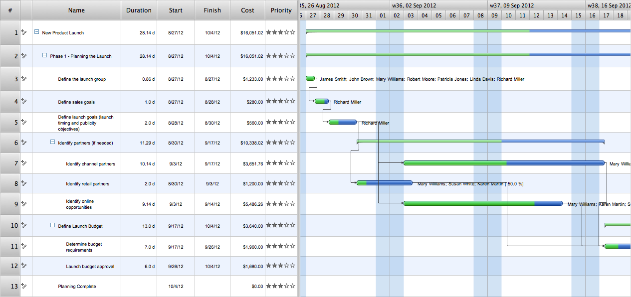
ConceptDraw Office is the most effective tool for planning, tracking, and reporting all types of projects with strong management capabilities, user friendly functionality, and superior ease of use. In this tutorial video we will assist you in planning and managing a project using ConceptDraw Office.
 Chemical and Process Engineering
This chemical engineering solution extends ConceptDraw PRO v.9.5 (or later) with process flow diagram symbols, samples, process diagrams templates and libraries of design elements for creating process and instrumentation diagrams, block flow diagrams (BFD
HelpDesk
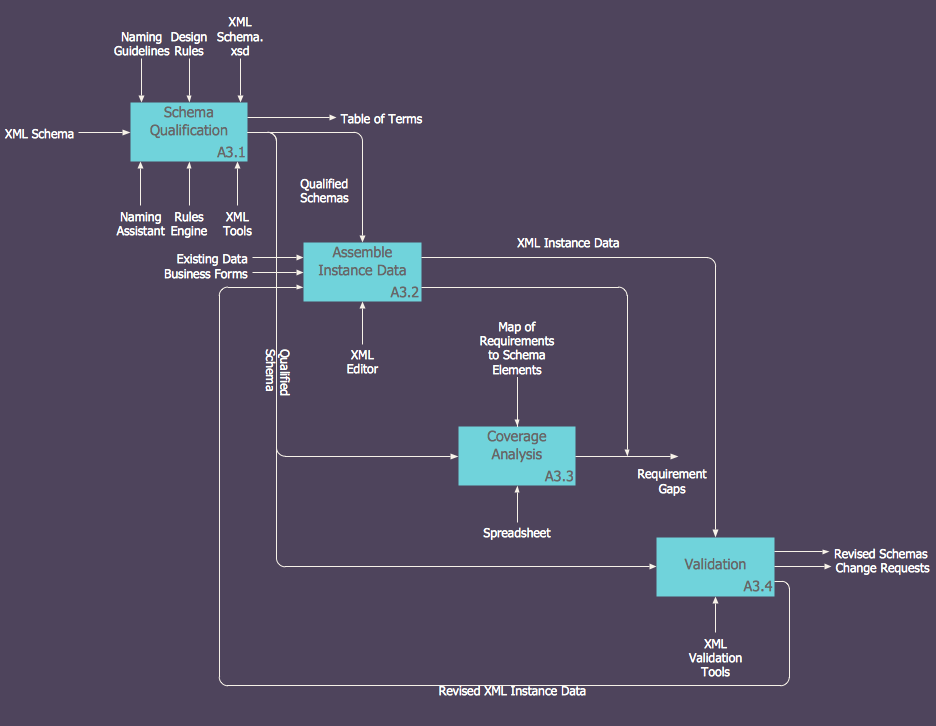
How to Create an IDEF0 Diagram for an Application Development
IDEF0 methods are intended to model the functions of a process, creating a graphical model that displays: what controls the function, who makes it, what resources are used and how they are connected with other functions. The IDEF0 tool is used to model the decisions, actions, and activities of a software system during the development process . IDEF0 diagram graphically depicts a model of a desired version of the application. ConceptDraw PRO allows you to create and communicate the IDEF0 diagrams of any complexity.- UML Class Diagram Tutorial | How to Create an IDEF0 Diagram for ...
- ConceptDraw PRO The best Business Drawing Software | Mac ...
- ER diagram tool for OS X | Best Vector Drawing Application for Mac ...
- Event-driven Process Chain Diagrams EPC | Audio and Video ...
- UML Composite Structure Diagram | Data structure diagram with ...
- UML Class Diagram Example for Transport System | Global ...
- ConceptDraw PRO Compatibility with MS Visio | Illustration | Audio ...
- UML use case diagram - Banking system | How to Create a Bank ...
- Program Structure Diagrams | Diagramming Software for UML ...
- Rapid UML | Examples of Flowcharts, Org Charts and More | Office ...
- UML use case diagram - Project administrator
- UML Diagrams with ConceptDraw PRO | Rapid UML | ConceptDraw ...
- UML Class Diagram Example - Medical Shop
- One formula of professional mind mapping : input data + output data ...
- In searching of alternative to MS Visio for MAC and PC with ...
- ConceptDraw PRO The best Business Drawing Software ...
- ConceptDraw PRO ER Diagram Tool | Good Flow Chart app for Mac ...
- Business Process Diagram | Standard Universal Audio & Video ...
- UML Diagrams with ConceptDraw PRO | In searching of alternative ...
- Create Flow Chart on Mac | UML Diagrams with ConceptDraw PRO ...


