The vector stencils library "Heating equipment" contains 42 symbols of regenerators, intercoolers, heaters, and condensers.
Use these shapes for drawing cooling systems, heat recovery systems, thermal, heat transfer and mechanical design, and process flow diagrams (PFD).
"Heating or cooling of processes, equipment, or enclosed environments are within the purview of thermal engineering.
One or more of the following disciplines may be involved in solving a particular thermal engineering problem:
Thermodynamics,
Fluid mechanics,
Heat transfer,
Mass transfer.
Thermal engineering may be practiced by mechanical engineers and chemical engineers.
One branch of knowledge used frequently in thermal engineering is that of thermofluids." [Thermal engineering. Wikipedia]
The design elements example "Heating equipment" was created using the ConceptDraw PRO diagramming and vector drawing software extended with the Chemical and Process Engineering solution from the Engineering area of ConceptDraw Solution Park.
Heating equipment symbols

"HVAC (stands for Heating, Ventilation and Air Conditioning) is a control system that applies regulation to a heating and/ or air conditioning system. Usually a sensing device is used to compare the actual state (e.g., temperature) with a target state. Then the control system draws a conclusion what action has to be taken (e.g., start the blower).
More complex HVAC systems can interface to Building Automation System (BAS) to allow the building owners to have more control over the heating or cooling units. The building owner can monitor the system and respond to alarms generated by the system from local or remote locations." [HVAC control system. Wikipedia]
The vector stencils library "HVAC control equipment" contains 48 symbols of heating, ventilation, air conditioning, refrigeration and automated building control equipment.
Use the design elements library HVAC control equipment to draw HVAC plans, schematic diagrams of heating, ventilation, air conditioning, refrigeration and automated building control systems, environmental control design building plans and equipment layouts using the ConceptDraw PRO diagramming and vector drawing software.
The shapes library HVAC control equipment is contained in the HVAC Plans solution from the Building Plans area of ConceptDraw Solution Park.
HVAC control equipment symbols

The vector stencils library "HVAC ductwork" contains 55 ducts, vents and HVAC mechanical components symbols.
Use the design elements library "HVAC ductwork" for drawing the HVAC ductwork system diagrams, heating, ventilation, air conditioning, refrigeration, automated building control and environmental control system layout floor plans.
"Ducts are used in heating, ventilation, and air conditioning (HVAC) to deliver and remove air. These needed airflows include, for example, supply air, return air, and exhaust air. Ducts also deliver, most commonly as part of the supply air, ventilation air. As such, air ducts are one method of ensuring acceptable indoor air quality as well as thermal comfort.
A duct system is often called ductwork. Planning ('laying out'), sizing, optimizing, detailing, and finding the pressure losses through a duct system is called duct design." [Duct (HVAC). Wikipedia]
The shapes library "HVAC ductwork" is included in the HVAC Plans solution from the Building Plans area of ConceptDraw Solution Park.
HVAC ductwork symbols

The vector stencils library "HVAC equipment" contains 26 symbols of HVAC equipment as pumps, fans, condensers, pipe coils, silencers, etc.
Use the design elements library "HVAC equipment" for drawing the HVAC system diagrams, heating, ventilation, air conditioning, refrigeration, automated building control and environmental control system layout floor plans using the ConceptDraw PRO diagramming and vector drawing software.
"HVAC (heating, ventilation, and air conditioning) is the technology of indoor and vehicular environmental comfort. HVAC system design is a subdiscipline of mechanical engineering, based on the principles of thermodynamics, fluid mechanics, and heat transfer. Refrigeration is sometimes added to the field's abbreviation as HVAC&R or HVACR, or ventilating is dropped as in HACR (such as the designation of HACR-rated circuit breakers).
HVAC is important in the design of medium to large industrial and office buildings such as skyscrapers and in marine environments such as aquariums, where safe and healthy building conditions are regulated with respect to temperature and humidity, using fresh air from outdoors." [HVAC. Wikipedia]
The shapes library "HVAC equipment" is contained in the HVAC Plans solution from the Building Plans area of ConceptDraw Solution Park.
HVAC equipment symbols

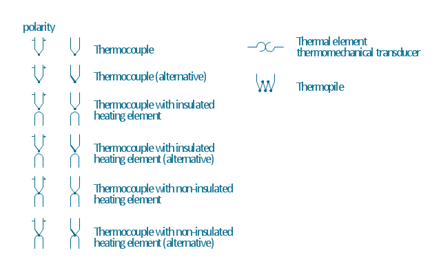
The vector stencils library "Thermo" contains 14 symbols of thermoelectric elements: thermal element, thermocouples with and without heating elements, thermoplile.
Use it for drawing electrical layouts, electronic schematics, and circuit diagrams.
"The thermoelectric effect is the direct conversion of temperature differences to electric voltage and vice versa. A thermoelectric device creates voltage when there is a different temperature on each side. Conversely, when a voltage is applied to it, it creates a temperature difference. At the atomic scale, an applied temperature gradient causes charge carriers in the material to diffuse from the hot side to the cold side.
This effect can be used to generate electricity, measure temperature or change the temperature of objects. Because the direction of heating and cooling is determined by the polarity of the applied voltage, thermoelectric devices can be used as temperature controllers.
The term "thermoelectric effect" encompasses three separately identified effects: the Seebeck effect, Peltier effect, and Thomson effect. Textbooks may refer to it as the Peltier–Seebeck effect. ...
Thermocouples and thermopiles are devices that use the Seebeck effect to measure the temperature difference between two objects, one connected to a voltmeter and the other to the probe. The temperature of the voltmeter, and hence that of the material being measured by the probe, can be measured separately using cold junction compensation techniques." [Thermoelectric effect. Wikipedia]
The shapes example "Design elements - Thermo" was drawn using the ConceptDraw PRO diagramming and vector drawing software extended with the Electrical Engineering solution from the Engineering area of ConceptDraw Solution Park.
Thermoelectric elements
- Heating Element Schematic Symbol
- Electrical Symbols — Thermo | Design elements - Heating ...
- Central Heating Symbols
- Electrical Symbols — Thermo | Design elements - Thermo | Design ...
- Design elements - Heating equipment | Electrical Symbols ...
- Electrical Symbols — Thermo | Thermo - Vector stencils library ...
- Symbol For Water Heater Element
- Electrical Symbols — Thermo | Design elements - Thermo | Piping ...
- Interior Design Plumbing - Design Elements | Heater Electrical ...
- Design elements - Thermo | Temp Probe Symbol Electronics
- Electrical Symbols — Thermo | Thermo - Vector stencils library ...
- HVAC Business Plan | Heating Coil Pfd Symbol
- Draw A Type Of A Heating Element
- Process Flow Diagram Symbols | Design elements - Heating ...
- Symbol Of Condenser In Flow Sheet
- Design elements - Heating equipment | Design elements - HVAC ...
- Electrical Symbols — Thermo | Electrical Symbols — Analog and ...
- Design elements - HVAC control equipment | HVAC Business Plan ...
- Schematic Symbol Of Heating Coil
- Water Heater Switch Symbol
- ERD | Entity Relationship Diagrams, ERD Software for Mac and Win
- Flowchart | Basic Flowchart Symbols and Meaning
- Flowchart | Flowchart Design - Symbols, Shapes, Stencils and Icons
- Flowchart | Flow Chart Symbols
- Electrical | Electrical Drawing - Wiring and Circuits Schematics
- Flowchart | Common Flowchart Symbols
- Flowchart | Common Flowchart Symbols