Cisco Network Topology. Cisco icons, shapes, stencils and symbols

Cisco Products Additional. Cisco icons, shapes, stencils and symbols

 Wireless Networks
The Wireless Networks Solution extends ConceptDraw DIAGRAM software with professional diagramming tools, set of wireless network diagram templates and samples, comprehensive library of wireless communications and WLAN objects to help network engineers and designers efficiently design and create Wireless network diagrams that illustrate wireless networks of any speed and complexity, and help to identify all required equipment for construction and updating wireless networks, and calculating their costs.
The vector stencils library "Wireless networks" contains 82 icon symbols for drawing wireless computer network diagrams and equipment layout plans.
"A wireless network is any type of computer network that uses wireless data connections for connecting network nodes.
Wireless networking is a method by which homes, telecommunications networks and enterprise (business) installations avoid the costly process of introducing cables into a building, or as a connection between various equipment locations.
Wireless telecommunications networks are generally implemented and administered using radio communication. This implementation takes place at the physical level (layer) of the OSI model network structure.
Examples of wireless networks include cell phone networks, Wi-Fi local networks and terrestrial microwave networks." [Wireless network. Wikipedia]
The clip art example "Wireless networks - Vector stencils library" was created using the ConceptDraw PRO diagramming and vector drawing software extended with the Wireless Networks solution from the Computer and Networks area of ConceptDraw Solution Park.
www.conceptdraw.com/ solution-park/ wireless-networks
Building 1
Building 4
Coverage (Blue)
-wireless-networks---vector-stencils-library.png--diagram-flowchart-example.png)
Wireless Connectivity

Network Cloud

Cloud

Wi-Fi Access

Tree

Computer
Laptop Computer
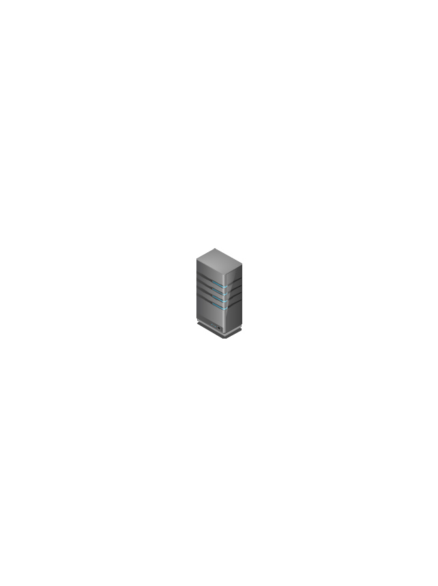
Server
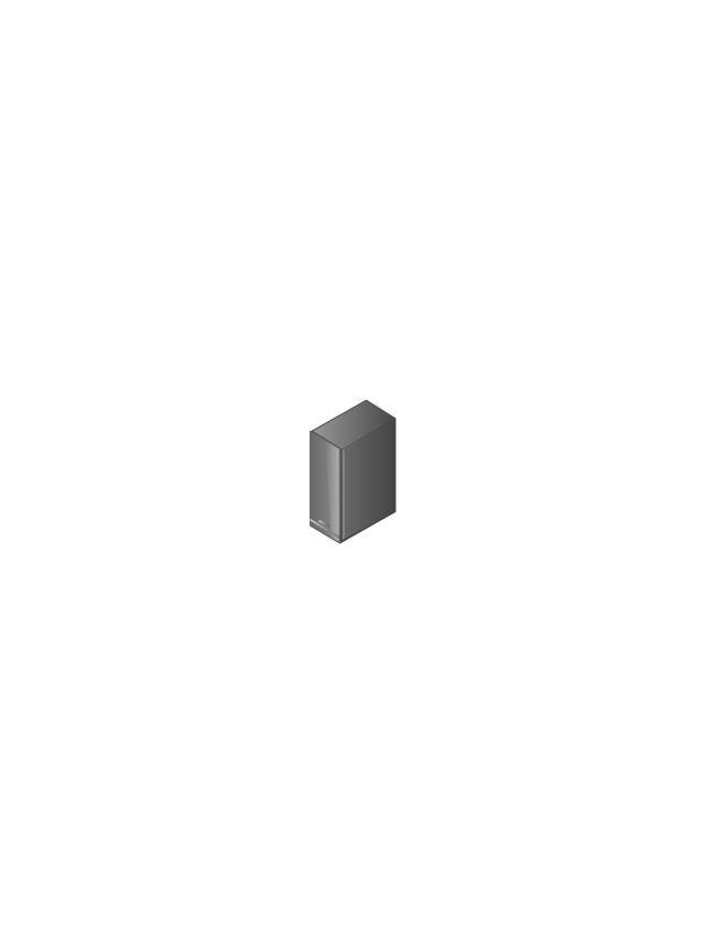
Wireless Network Storage
Router
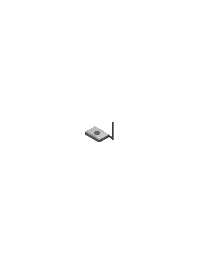
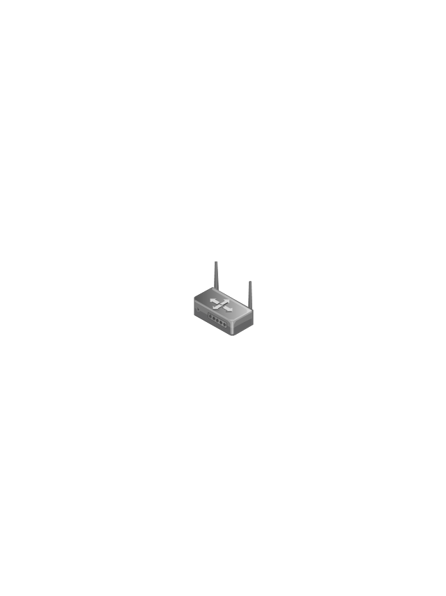
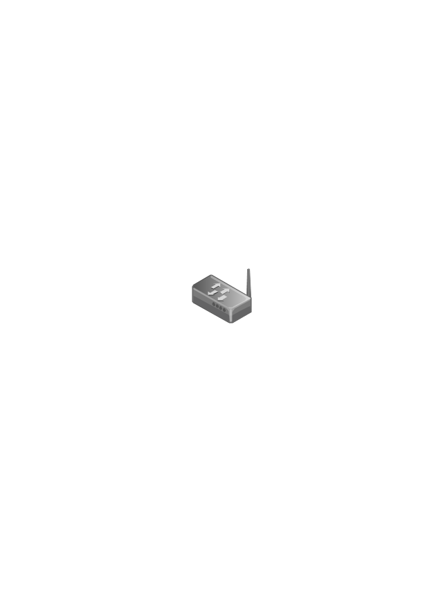
Wireless Router
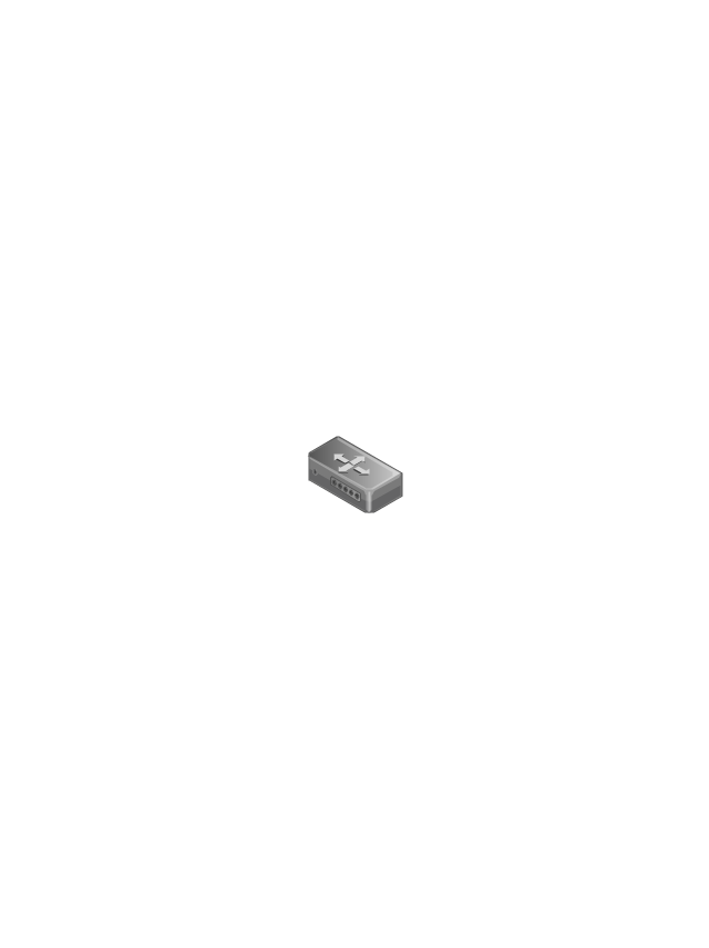
Switch
Wireless Access Point
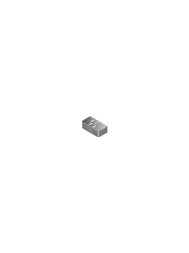
1U Hub Switch

2U Hub Switch
1U Server

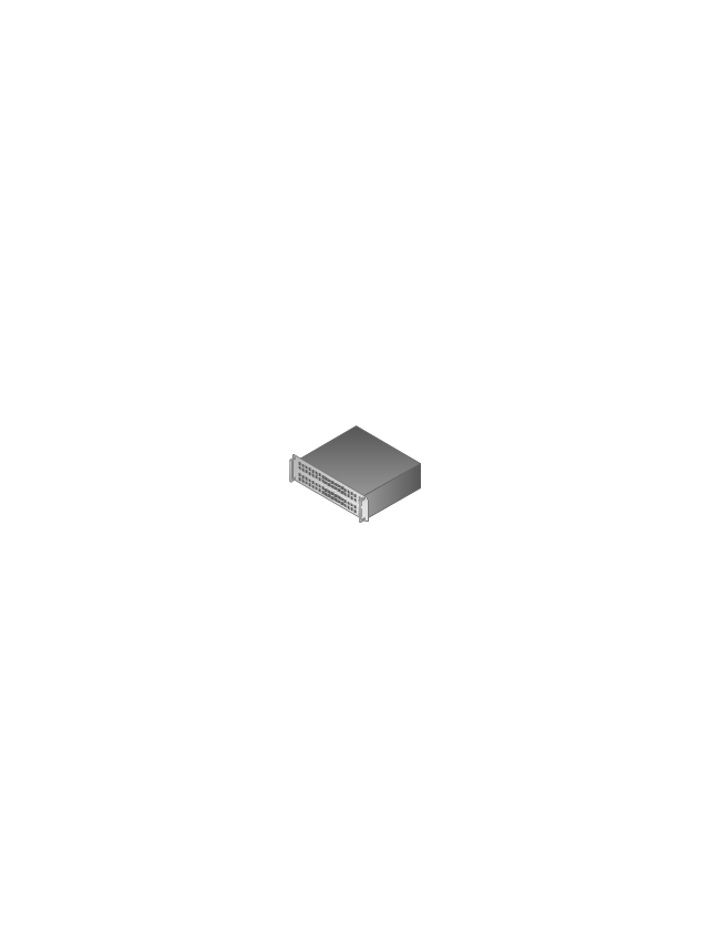
2U Server

3U Server

4U Server

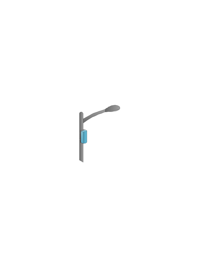
Outdoor Access Point
Indoor Access Point

Outdoor Wi-Fi Access Point

Access Point

Outdoor Mesh Node
Outdoor Mesh Node
Outdoor Access Node
Outdoor Access Node

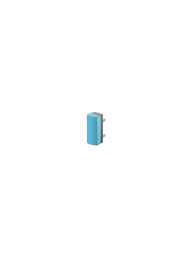
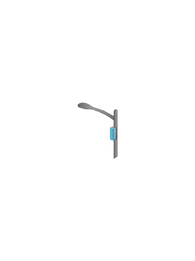
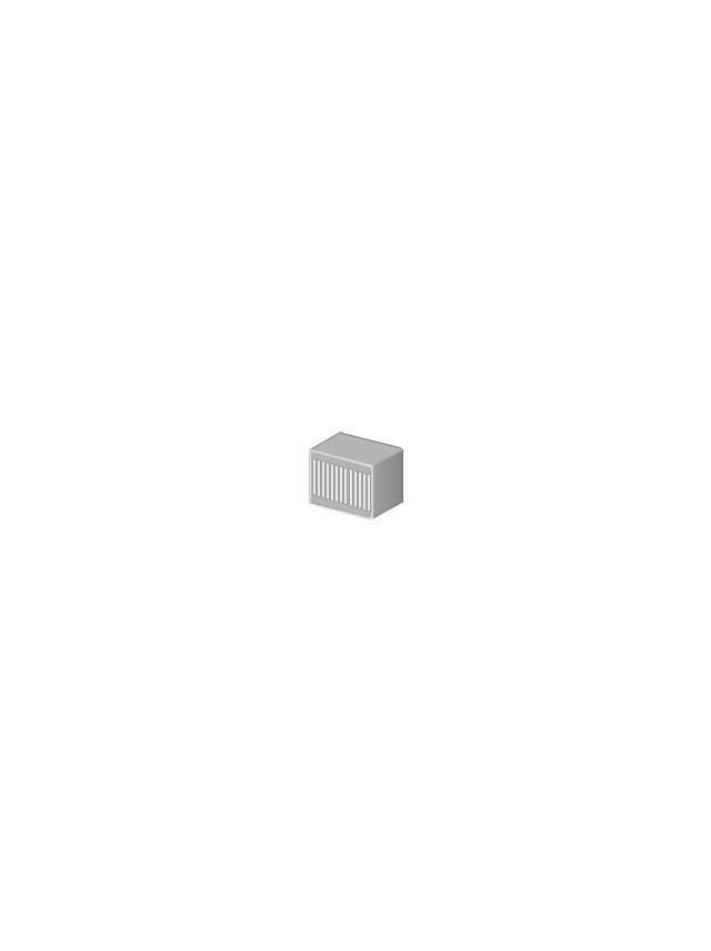
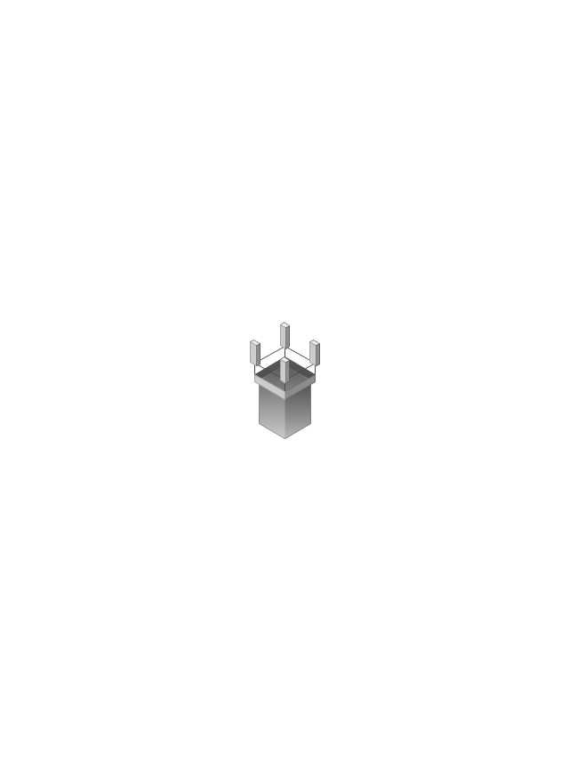
Base Station
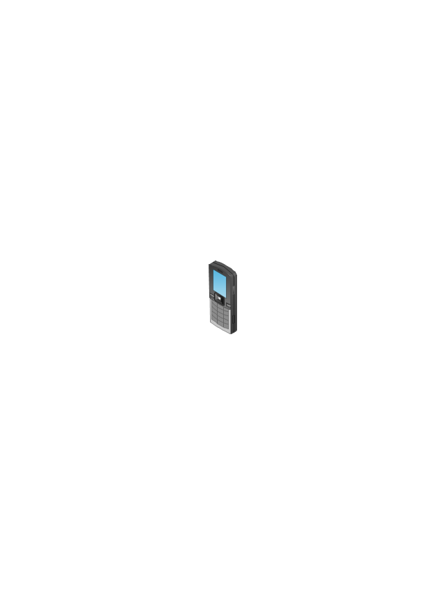
Cellular Phone
Outdoor Mesh Node
Active Directory Server
Smart WLAN Controller

Smart WLAN Controller

Smart Wi-Fi Access Point
Indoor Wi-Fi Access Point

Firewall
Coverage (Yellow)
-wireless-networks---vector-stencils-library.png--diagram-flowchart-example.png)
Coverage (O-Shaped)
-wireless-networks---vector-stencils-library.png--diagram-flowchart-example.png)
Outdoor Mesh Node
Electrical Symbols, Electrical Diagram Symbols

Wireless Network Mode

UML Class Diagram Notation

Cisco Network Design. Cisco icons, shapes, stencils, symbols and design elements

 Computer Network Diagrams
Computer Network Diagrams solution extends ConceptDraw DIAGRAM software with samples, templates and libraries of vector icons and objects of computer network devices and network components to help you create professional-looking Computer Network Diagrams, to plan simple home networks and complex computer network configurations for large buildings, to represent their schemes in a comprehensible graphical view, to document computer networks configurations, to depict the interactions between network's components, the used protocols and topologies, to represent physical and logical network structures, to compare visually different topologies and to depict their combinations, to represent in details the network structure with help of schemes, to study and analyze the network configurations, to communicate effectively to engineers, stakeholders and end-users, to track network working and troubleshoot, if necessary.
The vector stencils library "Cisco network topology" contains 89 symbols of Cisco network devices and design elements for drawing computer network topology diagrams.
"There are two basic categories of network topologies:
(1) Physical topologies,
(2) Logical topologies.
The shape of the cabling layout used to link devices is called the physical topology of the network. This refers to the layout of cabling, the locations of nodes, and the interconnections between the nodes and the cabling. The physical topology of a network is determined by the capabilities of the network access devices and media, the level of control or fault tolerance desired, and the cost associated with cabling or telecommunications circuits.
The logical topology in contrast, is the way that the signals act on the network media, or the way that the data passes through the network from one device to the next without regard to the physical interconnection of the devices." [Network topology. Wikipedia]
The symbols example "Cisco network topology - Vector stencils library" was created using the ConceptDraw PRO diagramming and vector drawing software extended with the Cisco Network Diagrams solution from the Computer and Networks area of ConceptDraw Solution Park.
www.conceptdraw.com/ solution-park/ computer-networks-cisco
Router

Broadband router

Router firewall

Wireless router

Workgroup switch

ATM switch

ISDN switch

Multilayer switch

Protocol translator

Communications server

Transpath

Bridge

Terminal server

Route switch processor

Content engine (cache director)
-cisco-network-topology---vector-stencils-library.png--diagram-flowchart-example.png)
Management engine (ME 1100)
-cisco-network-topology---vector-stencils-library.png--diagram-flowchart-example.png)
Switch processor

ITP

Voice gateway

BBSM

ATA

SIP Proxy server

NetRanger

Cisco 1000

IP

System controller

ACE

Directory server

ADM

Cisco Unity Express

Unity server

Cisco security

CallManager

DSLAM

H.323

CDM (Content Distribution Manager)
-cisco-network-topology---vector-stencils-library.png--diagram-flowchart-example.png)
ICM

Access point

Wireless bridge

Wireless connectivity

Guard

Mobile access router

Carrier Routing System (CRS)
-cisco-network-topology---vector-stencils-library.png--diagram-flowchart-example.png)
Vault

Workstation

PC

Macintosh

Cloud, gold

Cloud, white

Cloud, standard color

Cisco security management

PBX

DPT

Government building

Headquarters, blue

Router in building

Man

Woman

Workgroup switch, subdued

Router, subdued

File server

Firewall, horizontal

Firewall, vertical

Firewall, vertical, subdued

Lock

Key

Lock and key

Car

Truck

File cabinet

Breakout box

Breakout box, blue

Host

Relational database

Modem

BBS (Bulletin Board System)
-cisco-network-topology---vector-stencils-library.png--diagram-flowchart-example.png)
Satellite

Satellite dish

UPS

RPS

MAU

PAD

PAD X.28

Diskette

Contact center

Page icon
Antenna

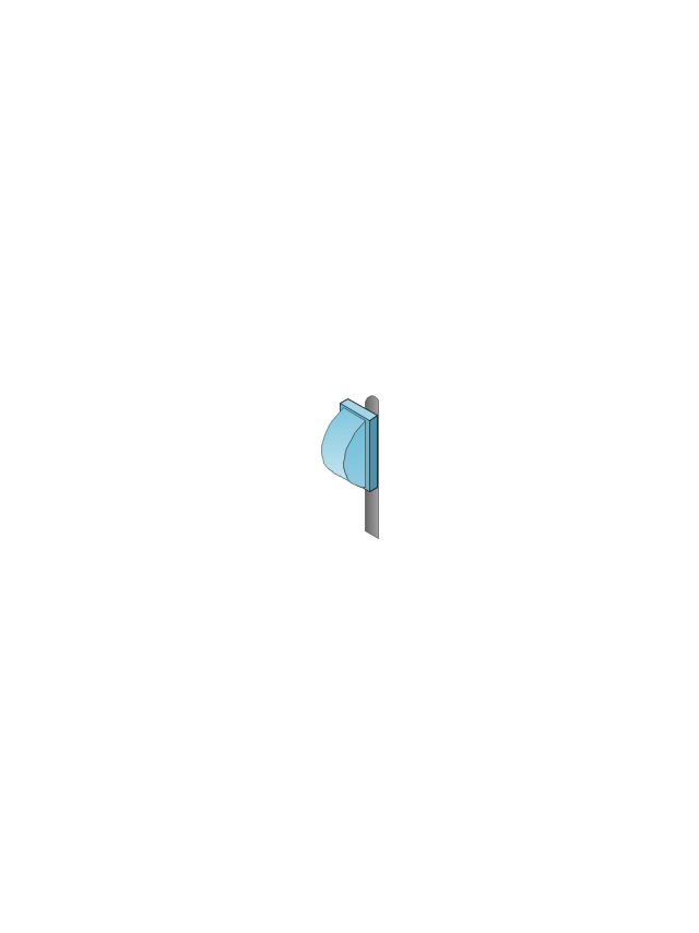
Antenna, blue

Radio tower

- Wireless Controller Visio Icon
- Sdn Controller Icon
- Wireless Lan Controller Symbol For Visio
- Sdn Controller Shape For Visio
- Wireless Network Diagram Examples | 3g Base Station Controller Icon
- Cisco Wireless Controller Visio Stencil
- Telecommunication Network Diagrams | Tranzeo - Vector stencils ...
- Cisco network topology - Vector stencils library | Visio Pabx Icon
- Network Diagram With Wireless Controller
- Cisco Switches and Hubs. Cisco icons , shapes, stencils and ...