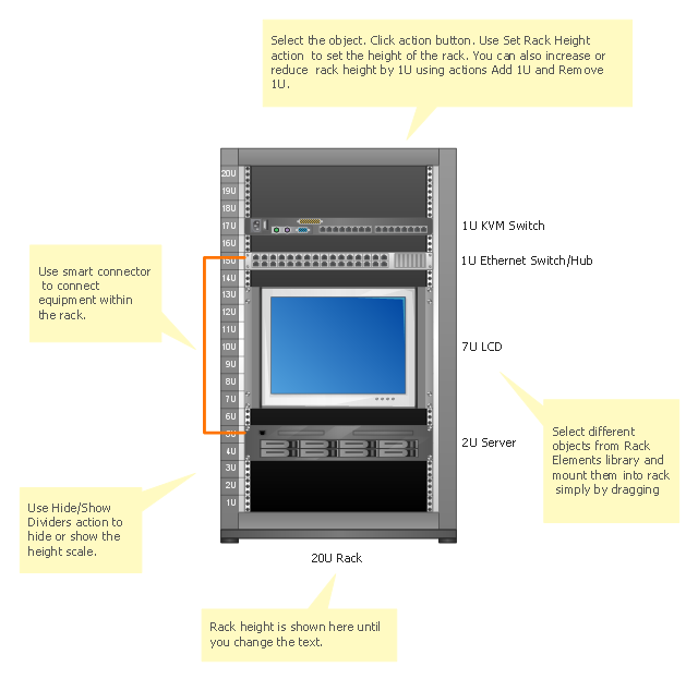
The vector stencils library "Rack diagrams" contains 55 hardware symbols for creating the server rack layout diagrams using the ConceptDraw PRO diagramming and vector drawing software.
"A 19-inch rack is a standardized frame or enclosure for mounting multiple equipment modules. Each module has a front panel that is 19 inches wide, including edges or ears that protrude on each side which allow the module to be fastened to the rack frame with screws. Equipment designed to be placed in a rack is typically described as rack-mount, rack-mount instrument, a rack mounted system, a rack mount chassis, subrack, rack mountable, or occasionally simply shelf. The industry standard rack cabinet is 42U tall." [19-inch rack. Wikipedia]
"A rack unit, U or RU is a unit of measure that describes the height of equipment designed to mount in a 19-inch rack or a 23-inch rack. The size of a piece of rack-mounted equipment is frequently described as a number in "U". For example, one rack unit is often referred to as "1U", 2 rack units as "2U" and so on.
A typical full size rack is 42U, which means it holds just over 6 feet of equipment, and a typical "half-height" rack would be 18-22U, or around 3 feet high." [Rack unit. Wikipedia]
The example "Design elements - Rack diagram" is included in the Rack Diagrams solution from the Computer and Networks area of ConceptDraw Solution Park.
Rack diagram elements
Server rack diagrams visualize the the rack mounting of computer and network equipment as the drawing of frontal view of the rack with equipment installed. They are used for choosing the equipment or racks to buy, and help to organize equipment on the racks virtually, without the real installation.
"A 19-inch rack is a standardized frame or enclosure for mounting multiple equipment modules. Each module has a front panel that is 19 inches (482.6 mm) wide, including edges or ears that protrude on each side which allow the module to be fastened to the rack frame with screws." [19-inch rack. Wikipedia]
"A rack unit, U or RU is a unit of measure that describes the height of equipment designed to mount in a 19-inch rack or a 23-inch rack. The 19-inch (482.6 mm) or 23-inch (584.2 mm) dimension refers to the width of the equipment mounting frame in the rack including the frame; the width of the equipment that can be mounted inside the rack is less. One rack unit is 1.75 inches (4.445 cm) high.
The size of a piece of rack-mounted equipment is frequently described as a number in "U". For example, one rack unit is often referred to as "1U", 2 rack units as "2U" and so on.
A typical full size rack is 42U, which means it holds just over 6 feet of equipment, and a typical "half-height" rack would be 18-22U, or around 3 feet high." [Rack unit. Wikipedia]
The rack diagram template is included in the Rack Diagrams solution from the Computer and Networks area of ConceptDraw Solution Park.
Rack diagram template
This sport field plan sample was designed on the base of the Wikipedia file: VolleyballCourt.svg. [en.wikipedia.org/ wiki/ File:VolleyballCourt.svg]
This file is licensed under the Creative Commons Attribution-Share Alike 3.0 Unported license. [creativecommons.org/ licenses/ by-sa/ 3.0/ deed.en]
"Volleyball is a team sport in which two teams of six players are separated by a net. Each team tries to score points by grounding a ball on the other team's court under organized rules. It has been a part of the official program of the Summer Olympic Games since 1964. ...
The court dimensions.
A volleyball court is 18 m (59 ft) long and 9 m (29.5 ft) wide, divided into 9 m × 9 m halves by a one-meter (40-inch) wide net. The top of the net is 2.43 m (8 ft 0 in) above the center of the court for men's competition, and 2.24 m (7 ft 4 in) for women's competition, varied for veterans and junior competitions.
The minimum height clearance for indoor volleyball courts is 7 m (23 ft), although a clearance of 8 m (26 ft) is recommended.
A line 3 m (9.84 ft) from and parallel to the net is considered the "attack line". This "3 meter" (or "10-foot") line divides the court into "back row" and "front row" areas (also back court and front court). These are in turn divided into 3 areas each: these are numbered as follows, starting from area "1", which is the position of the serving player.
After a team gains the serve (also known as siding out), its members must rotate in a clockwise direction, with the player previously in area "2" moving to area "1" and so on, with the player from area "1" moving to area "6".
The team courts are surrounded by an area called the free zone which is a minimum of 3 meters wide and which the players may enter and play within after the service of the ball. All lines denoting the boundaries of the team court and the attack zone are drawn or painted within the dimensions of the area and are therefore a part of the court or zone. If a ball comes in contact with the line, the ball is considered to be "in". An antenna is placed on each side of the net perpendicular to the sideline and is a vertical extension of the side boundary of the court. A ball passing over the net must pass completely between the antennae (or their theoretical extensions to the ceiling) without contacting them." [Volleyball. Wikipedia]
The sport field plan example "Volleyball court dimensions" was created using the ConceptDraw PRO diagramming and vector drawing software extended with the Sport Field Plans solution from the Building Plans area of ConceptDraw Solution Park.
Sport field plan

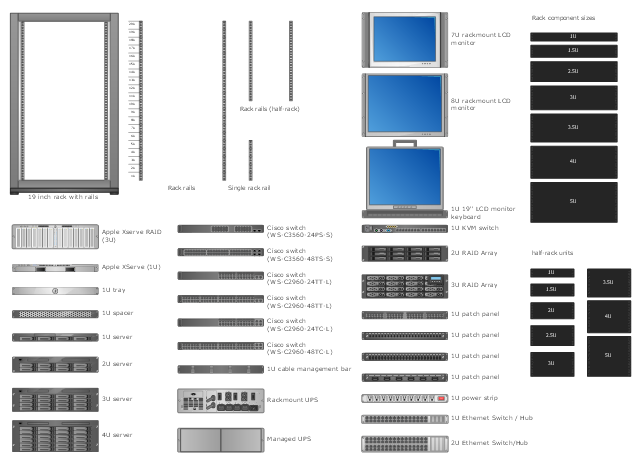
The vector stencils library "Rack diagrams" contains 33 rack design elements for drawing the computer network server rack diagrams.
"A 19-inch rack is a standardized frame or enclosure for mounting multiple equipment modules. Each module has a front panel that is 19 inches (482.6 mm) wide, including edges or ears that protrude on each side which allow the module to be fastened to the rack frame with screws. ...
Equipment designed to be placed in a rack is typically described as rack-mount, rack-mount instrument, a rack mounted system, a rack mount chassis, subrack, rack mountable, or occasionally simply shelf. The height of the electronic modules is also standardized as multiples of 1.75 inches (44.45 mm) or one rack unit or U (less commonly RU). The industry standard rack cabinet is 42U tall. ...
19-inch racks in 2-post or 4-post form hold most equipment in modern data centers, ISP facilities and professionally designed corporate server rooms. They allow for dense hardware configurations without occupying excessive floorspace or requiring shelving." [19-inch rack. Wikipedia]
The clip art example "Rack diagrams - Vector stencils library" was created using the ConceptDraw PRO diagramming and vector drawing software extended with the Rack Diagrams solution from the Computer and Networks area of ConceptDraw Solution Park.
19 inch Rack with Rails

Rack

Rack rails

Rack rails (half-width)
-rack-diagrams---vector-stencils-library.png--diagram-flowchart-example.png)
Single rack rail

Xserve RAID

XServe

1U tray

1U spacer

2U server

1U Ethernet Switch/Hub

2U Ethernet Switch/Hub

1U power strip

1U KVM switch

1U patch panel

Rackmount UPS

Cisco switch (WS-C3560-24PS-S)
-rack-diagrams---vector-stencils-library.png--diagram-flowchart-example.png)
Cisco switch (WS-C3560-48TS-S)
-rack-diagrams---vector-stencils-library.png--diagram-flowchart-example.png)
Cisco switch (WS-C2960-48TT-L)
-rack-diagrams---vector-stencils-library.png--diagram-flowchart-example.png)
Cisco switch (WS-C2960-48TC-L)
-rack-diagrams---vector-stencils-library.png--diagram-flowchart-example.png)
Cisco switch (WS-C2960-24TT-L)
-rack-diagrams---vector-stencils-library.png--diagram-flowchart-example.png)
Cisco switch (WS-C2960-24TC-L)
-rack-diagrams---vector-stencils-library.png--diagram-flowchart-example.png)
7U rackmount LCD monitor

8U rackmount LCD monitor

Fiber optic patch panel (type A)
-rack-diagrams---vector-stencils-library.png--diagram-flowchart-example.png)
Fiber optic patch panel (type B)
-rack-diagrams---vector-stencils-library.png--diagram-flowchart-example.png)
Fiber optic patch panel (type C)
-rack-diagrams---vector-stencils-library.png--diagram-flowchart-example.png)
3U server

2U RAID array

3U RAID array

Managed UPS

1U 19'' LCD monitor keyboard

1U server

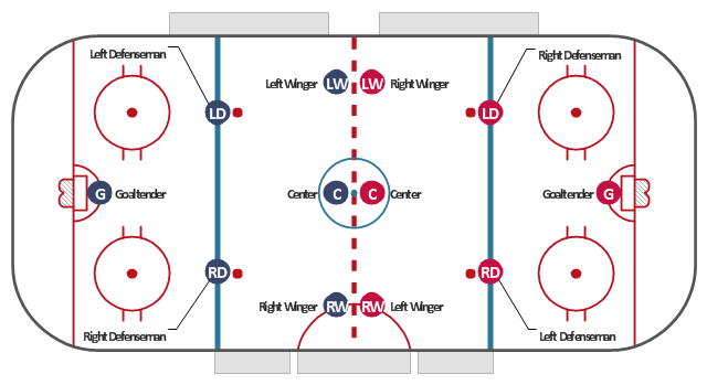
"An ice hockey rink is an ice rink that is specifically designed for ice hockey, a team sport. It is rectangular with rounded corners and surrounded by a wall approximately 1 meter (40-48 inches) high called the boards." [Ice hockey rink. Wikipedia]
"A team usually consists of four lines of three forwards, three pairs of defensemen, and two goalies. Five members of each team skate up and down the ice trying to take the puck and score a goal against the opposing team. Each team has a goaltender who tries to stop the puck from going into the goal." [Ice hockey. Wikipedia]
This ice hockey rink diagram was redesigned from the Wikimedia Commons file: Ice hockey rink with players russian.svg.
[commons.wikimedia.org/ wiki/ File:Ice_ hockey_ rink_ with_ players_ russian.svg]
This file is licensed under the Creative Commons Attribution-Share Alike 3.0 Unported license. [creativecommons.org/ licenses/ by-sa/ 3.0/ deed.en]
The diagram example "Ice hockey rink with players" was created using the ConceptDraw PRO diagramming and vector drawing software extended with the Hockey solution from the Sport area of ConceptDraw Solution Park.
Ice hockey rink diagram
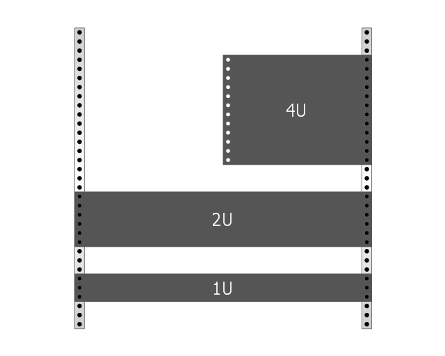
This rack diagram example was redesigned from the Wikimedia Commons file: Rackunit.svg. [commons.wikimedia.org/ wiki/ File:Rackunit.svg]
Rack with sample component sizes including an A/ V half-rack unit.
"A rack unit, U or RU as a unit of measure describes the height of equipment[which?] designed to mount in a 19-inch rack or a 23-inch rack. The 19-inch (482.6 mm) or 23-inch (584.2 mm) dimension reflects the width of the equipment mounting-frame in the rack including the frame; the width of the equipment that can be mounted inside the rack is less. One rack unit is 1.75 inches (4.445 cm) high. (This equates to one vershok, an obsolete unit of measurement used officially in Russia until 1924.)
The size of a piece of rack-mounted equipment is frequently described as a number in "U". For example, one rack unit is often referred to as "1U", 2 rack units as "2U" and so on." [Rack unit. Wikipedia]
The example "Rack with sample component sizes including an A/ V half-rack unit" was created using the ConceptDraw PRO diagramming and vector drawing software extended with the Rack Diagrams solution from the Computer and Networks area of ConceptDraw Solution Park.
Rack with sample component sizes
The vector stencils library Registers, drills and diffusers contains 47 symbols of rectangular, circular, linear and troffer air handling inlet/ outlet components.
Use the design elements library Registers, drills and diffusers to draw reflected ceiling plans (RCP) and HVAC layout floor plans using the ConceptDraw PRO diagramming and vector drawing software.
"A ceiling is an overhead interior surface that covers the upper limit of a room. It is not generally considered a structural element, but a finished surface concealing the underside of the floor or roof structure above.
Ceilings are classified according to their appearance or construction. A cathedral ceiling is any tall ceiling area similar to those in a church. A dropped ceiling is one in which the finished surface is constructed anywhere from a few inches to several feet below the structure above it. This may be done for aesthetic purposes, such as achieving a desirable ceiling height; or practical purposes such as providing a space for HVAC or piping. An inverse of this would be a raised floor. A concave or barrel shaped ceiling is curved or rounded, usually for visual or acoustical value, while a coffered ceiling is divided into a grid of recessed square or octagonal panels, also called a "lacunar ceiling". A cove ceiling uses a curved plaster transition between wall and ceiling; it is named for cove molding, a molding with a concave curve." [Ceiling. Wikipedia]
"... reflected Ceiling Plans (RCP)s showing ceiling layouts appear after the floor plans." [Plan (drawing). Wikipedia]
The shapes library "Registers, drills and diffusers" is contained in the Reflected Ceiling Plans solution from the Building Plans area of ConceptDraw Solution Park.
Reflected ceiling plan symbols

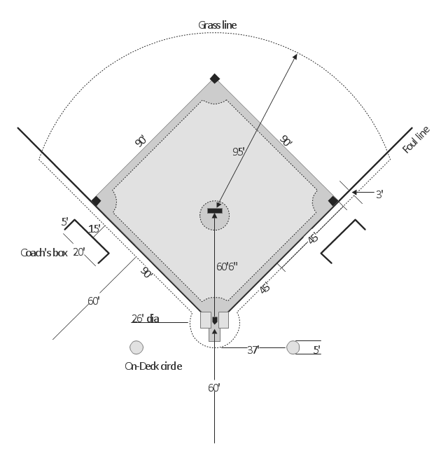
"A baseball field, also called a ball field or a baseball diamond, is the field upon which the game of baseball is played. The term is also used as a metonym for baseball park. ...
The starting point for much of the action on the field is home plate, which is a five-sided slab of whitened rubber, 17-inches square with two of the corners removed so that one edge is 17 inches long, two adjacent sides are 8½ inches and the remaining two sides are 12 inches and set at an angle to make a point. Adjacent to each of the two parallel 8½-inch sides is a batter's box. The point of home plate where the two 12-inch sides meet at right angles, is at one corner of a ninety-foot square. The other three corners of the square, in counterclockwise order from home plate, are called first base, second base, and third base. Three canvas bags fifteen inches (38 cm) square mark the three bases. These three bags along with home plate form the four bases at the corners of the infield." [Baseball field. Wikipedia]
The diagram example "Baseball field" was created using the ConceptDraw PRO diagramming and vector drawing software extended with the Baseball solution from the Sport area of ConceptDraw Solution Park.
Baseball field diagram
Local area network (LAN). Computer and Network Examples
 diagram")

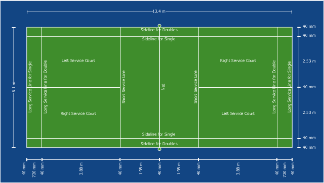
This sport field plan sample depicts the badminton court arena.
"The court is rectangular and divided into halves by a net. Courts are usually marked for both singles and doubles play, although badminton rules permit a court to be marked for singles only. The doubles court is wider than the singles court, but both are of same length. The exception, which often causes confusion to newer players, is that the doubles court has a shorter serve-length dimension.
The full width of the court is 6.1 metres (20 ft), and in singles this width is reduced to 5.18 metres (17 ft). The full length of the court is 13.4 metres (44 ft). The service courts are marked by a centre line dividing the width of the court, by a short service line at a distance of 1.98 metres (6 ft 6 inch) from the net, and by the outer side and back boundaries. In doubles, the service court is also marked by a long service line, which is 0.76 metres (2 ft 6 inch) from the back boundary.
The net is 1.55 metres (5 ft 1 inch) high at the edges and 1.524 metres (5 ft) high in the centre. The net posts are placed over the doubles sidelines, even when singles is played." [Badminton. Wikipedia]
The sport field plan example "Badminton court" was created using the ConceptDraw PRO diagramming and vector drawing software extended with the Sport Field Plans solution from the Building Plans area of ConceptDraw Solution Park.
Sport field plan
- Volleyball court dimensions | Volleyball Ground Measurement Wiki
- Rack diagrams - Vector stencils library | Rack diagram - Template ...
- Volleyball Equipment Wikipedia
- Dfd Symbols Wiki
- Volleyball Court Dimension Wikipedia
- Rack units | Rack Diagrams | Design elements - Rack diagram ...
- Hvac Drawing And Deaign Wikipedia
- Volleyball Equipment List Wikipedia
- 19 Inch Rack