Electrical and Telecom Plan Software

Physical Security Plan

Building Drawing Software for Designing Plumbing


The vector stencils library "Electrical and telecom" contains 83 symbols of electrical and telecommunication equipment for electrical drawings and wiring diagrams of buildings, communication centers, power plants and electrical distribution systems.
"An electrical drawing, is a type of technical drawing that shows information about power, lighting, and communication for an engineering or architectural project." [Electrical drawing. Wikipedia]
Use the design elements library "Electrical and telecom" to design your own electrical drawings, plot plans of the building outside electrical wiring, floor plans with electrical and telecommunication systems layout, power-riser diagrams with panel boards, control wiring diagrams and cabling layout schemes, reflected ceiling plans and lighting panels layouts using the ConceptDraw PRO diagramming and vector drawing software.
The shapes library "Electrical and telecom" is included in the Electric and Telecom Plans solution from the Building Plans area of ConceptDraw Solution Park.
Electrical and telecom symbols

This cafe electrical floor plan sample shows the outlet and switch layout.
"An electrical drawing, is a type of technical drawing that shows information about power, lighting, and communication for an engineering or architectural project. Any electrical working drawing consists of "lines, symbols, dimensions, and notations to accurately convey an engineering's design to the workers, who install the electrical system on the job".
A complete set of working drawings for the average electrical system in large projects usually consists of:
(1) A plot plan showing the building's location and outside electrical wiring.
(2) Floor plans showing the location of electrical systems on every floor.
(3) Power-riser diagrams showing panel boards.
(4) Control wiring diagrams.
(5) Schedules and other information in combination with construction drawings.
Electrical drafters prepare wiring and layout diagrams used by workers who erect, install, and repair electrical equipment and wiring in communication centers, power plants, electrical distribution systems, and buildings." [Electrical drawing. Wikipedia]
The outlet and switch layout example "Cafe electrical floor plan" was created using the ConceptDraw PRO diagramming and vector drawing software extended with the Electric and Telecom Plans solution from the Building Plans area of ConceptDraw Solution Park.
Outlet and switch layout

Network Diagram Software. LAN Network Diagrams. Physical Office Network Diagrams


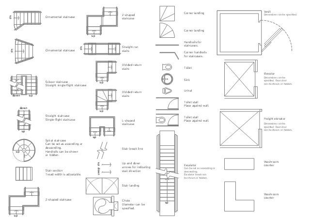
The design elements library Building core contains 80 symbols of stairs, elevators, escalators, restroom fixtures, and a safe.
Use the shapes library Building core to draw the structural diagrams, bathroom layouts, building automation, architectural drawings, and riser diagrams, as well as space plans, store and shopping mall plans, and facility planning, plant layouts using the ConceptDraw PRO diagramming and vector drawing software.
"In architecture and building engineering, a floor plan otherwise known as a Scottish plan is a drawing to scale, showing a view from above, of the relationships between rooms, spaces and other physical features at one level of a structure.
The term may be used in general to describe any drawing showing the physical layout of objects.
A floor plan could show:
Interior walls and hallways;
Restrooms;
Windows and doors;
Appliances such as stoves, refrigerators, water heater etc.;
Interior features such as fireplaces, saunas and whirlpools;
The use of all rooms shall be indicated." [Floor plan. Wikipedia]
The vector stencils library Building core is provided by the Floor Plans solution from the Building Plans area of ConceptDraw Solution Park.
Electrical Symbols, Electrical Diagram Symbols

Draw Fishbone Diagram on MAC Software

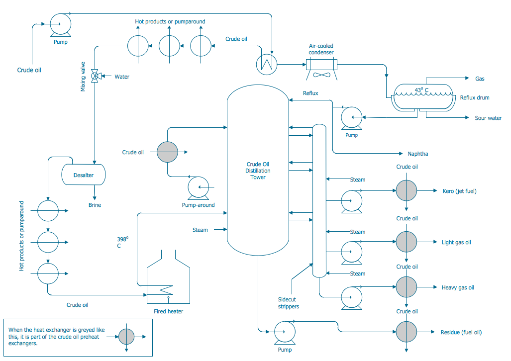
Process and Instrumentation Diagram
- Residential Electrical Riser Diagram
- Riser Diagram Symbols
- Telecommunication Risers Diagram
- How To Make An Electrical Riser Diagram
- Basic Building Electrical Riser Diagram
- How To Make Electric Riser Diagram
- Electrical Layout Riser Diagram Sample
- Electrical Riser Diagram For Duplex
- Riser Diagram Electrical Sample
- Telecom Cable Riser Diagram