 Entity-Relationship Diagram (ERD)
An Entity-Relationship Diagram (ERD) is a visual presentation of entities and relationships. That type of diagrams is often used in the semi-structured or unstructured data in databases and information systems. At first glance ERD is similar to a flowch
Entity Relationship Diagram Symbols

ERD Symbols and Meanings


"Chen's notation for entity–relationship modeling uses rectangles to represent entity sets, and diamonds to represent relationships appropriate for first-class objects: they can have attributes and relationships of their own. If an entity set participates in a relationship set, they are connected with a line.
Attributes are drawn as ovals and are connected with a line to exactly one entity or relationship set.
Cardinality constraints are expressed as follows:
- a double line indicates a participation constraint, totality or surjectivity: all entities in the entity set must participate in at least one relationship in the relationship set;
- an arrow from entity set to relationship set indicates a key constraint, i.e. injectivity: each entity of the entity set can participate in at most one relationship in the relationship set;
- a thick line indicates both, i.e. bijectivity: each entity in the entity set is involved in exactly one relationship.
- an underlined name of an attribute indicates that it is a key: two different entities or relationships with this attribute always have different values for this attribute.
Attributes are often omitted as they can clutter up a diagram; other diagram techniques often list entity attributes within the rectangles drawn for entity sets." [Entity–relationship model. Wikipedia]
The vector stencils library ERD, Chen's notation contains 13 symbols for drawing entity-relatinship diagrams using the ConceptDraw PRO diagramming and vector drawing software.
The example "Design elements - ER diagram (Chen notation)" is included in the Entity-Relationship Diagram (ERD) solution from the Software Development area of ConceptDraw Solution Park.
Chen's ERD
.png--diagram-flowchart-example.png)
This example was designed on the base of the Wikimedia Commons file: Weak entity ER-example.svg.
[commons.wikimedia.org/ wiki/ File:Weak_ entity_ ER-example.svg]
This file is licensed under the Creative Commons Attribution-Share Alike 3.0 Unported license. [creativecommons.org/ licenses/ by-sa/ 3.0/ deed.en]
"In a relational database, a weak entity is an entity that cannot be uniquely identified by its attributes alone; therefore, it must use a foreign key in conjunction with its attributes to create a primary key. The foreign key is typically a primary key of an entity it is related to.
In entity relationship diagrams, ER diagrams a weak entity set is indicated by a bold (or double-lined) rectangle (the entity) connected by a bold (or double-lined) type arrow to a bold (or double-lined) diamond (the relationship)." [Weak entity. Wikipedia]
The entity-relationship diagram example "Weak entity ERD" was drawn using ConceptDraw PRO software extended with the Entity-Relationship Diagram (ERD) solution from the Software Development area of ConceptDraw Solution Park.
Entity-relationship diagram
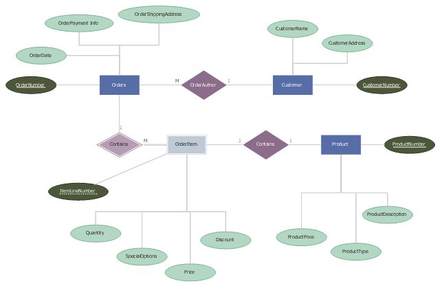
This ERD example was designed on the base of the entity-relationship diagram on the webpage "IS480 Team wiki: 2015T1 WhitePinnacle Documentation" from the Singapore Management University website. [wiki.smu.edu.sg/ is480/ IS480_ Team_ wiki%3A_ 2015T1_ WhitePinnacle_ Documentation]
This is ERD from the documentation of the High School Emergency Medical Responder (HS EMR) information system.
"Emergency medical responders are people who are specially trained to provide out-of-hospital care in medical emergencies. There are many different types of emergency medical responders, each with different levels of training, ranging from first aid and basic life support. Emergency Medical Responders have a very limited scope of practice and have the least amount of comprehensive education, clinical experience or clinical skills of EMS personnel. The Emergency Medical Responder (EMR) is not meant to replace the roles of Emergency Medical Technicians, Emergency Medical Technologists or Paramedics and their wide range of specialities. Emergency Medical Responders typically assist in rural regions providing basic life support where pre-hospital health professionals are not available due to limited resources or infrastructure." [Emergency medical responder. Wikipedia]
The example "Entity-Relationship Diagram" was drawn using ConceptDraw PRO software extended with the Entity-Relationship Diagram (ERD) solution from the Software Development area of ConceptDraw Solution Park.
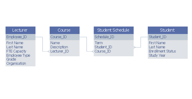
ERD
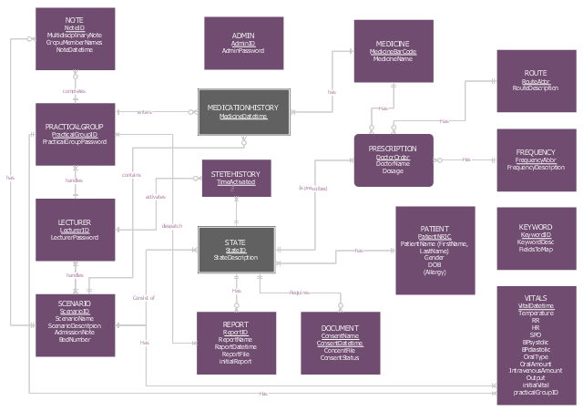
This example was designed on the base of Wikimedia Commons file: Example ERD2.png.
"example entity relationship diagram showing relationship between lecturers and students" [commons.wikimedia.org/ wiki/ File:Example_ ERD2.png]
This file is licensed under the Creative Commons Attribution-Share Alike 3.0 Unported license. [creativecommons.org/ licenses/ by-sa/ 3.0/ deed.en]
"Relationship diagrams (also known as logical data models) are used to design relational databases and can be a good way of understanding the structures in a data set. The 3 building blocks of an Entity Relationship model are entities, attributes and relationships. An entity is a discrete and recognisable 'thing', either a pysical object ..., or concept ... Each entity can be physically represented as a table, where each column of the table is an attribute of the entity ... A relationship is a verb that links two or more entities. ... Importantly, relationships also have a cardinality that can be 'one to one', 'many to one', 'one to many' or 'many to many'. ... Many to many relationships are often a sign that a design needs to be further elaborated. For example the 'teaches' relationship between teachers and students at a university would be many to many and would require the introduction of entities like class and date to fully understand the relationship." [en.wikibooks.org/ wiki/ Data_ Science:_ An_ Introduction/ Thinking_ Like_ a_ Data_ Engineer]
The entity-relationship diagram example "Lecturers-students relationship ERD" was drawn using ConceptDraw PRO software extended with the Entity-Relationship Diagram (ERD) solution from the Software Development area of ConceptDraw Solution Park.
Entity-relationship diagram
"Chen's notation for entity–relationship modeling uses rectangles to represent entity sets, and diamonds to represent relationships appropriate for first-class objects: they can have attributes and relationships of their own. If an entity set participates in a relationship set, they are connected with a line.
Attributes are drawn as ovals and are connected with a line to exactly one entity or relationship set.
Cardinality constraints are expressed as follows:
- a double line indicates a participation constraint, totality or surjectivity: all entities in the entity set must participate in at least one relationship in the relationship set;
- an arrow from entity set to relationship set indicates a key constraint, i.e. injectivity: each entity of the entity set can participate in at most one relationship in the relationship set;
- a thick line indicates both, i.e. bijectivity: each entity in the entity set is involved in exactly one relationship.
- an underlined name of an attribute indicates that it is a key: two different entities or relationships with this attribute always have different values for this attribute.
Attributes are often omitted as they can clutter up a diagram; other diagram techniques often list entity attributes within the rectangles drawn for entity sets." [Entity–relationship model. Wikipedia]
The vector stencils library ERD, Chen's notation contains 13 symbols for drawing entity-relatinship diagrams using the ConceptDraw PRO diagramming and vector drawing software.
The example "Design elements - ER diagram (Chen notation)" is included in the Entity-Relationship Diagram (ERD) solution from the Software Development area of ConceptDraw Solution Park.
Attributes are drawn as ovals and are connected with a line to exactly one entity or relationship set.
Cardinality constraints are expressed as follows:
- a double line indicates a participation constraint, totality or surjectivity: all entities in the entity set must participate in at least one relationship in the relationship set;
- an arrow from entity set to relationship set indicates a key constraint, i.e. injectivity: each entity of the entity set can participate in at most one relationship in the relationship set;
- a thick line indicates both, i.e. bijectivity: each entity in the entity set is involved in exactly one relationship.
- an underlined name of an attribute indicates that it is a key: two different entities or relationships with this attribute always have different values for this attribute.
Attributes are often omitted as they can clutter up a diagram; other diagram techniques often list entity attributes within the rectangles drawn for entity sets." [Entity–relationship model. Wikipedia]
The vector stencils library ERD, Chen's notation contains 13 symbols for drawing entity-relatinship diagrams using the ConceptDraw PRO diagramming and vector drawing software.
The example "Design elements - ER diagram (Chen notation)" is included in the Entity-Relationship Diagram (ERD) solution from the Software Development area of ConceptDraw Solution Park.
Chen's ERD
ER Diagram Tool

Entity Relationship Software

- Entity Relationship Diagram Wiki
- Erd Wiki
- Chen Notation | Design elements - ER diagram (Chen notation ...
- Er Diagram Wiki
- Er Diagram Symbols Wiki
- Event-driven Process Chain Diagrams | Entity-Relationship Diagram ...
- ERD Symbols and Meanings | Chen notation ERD of MMORPG ...
- Entity Relationship Diagram For Online Multi Player Game
- Entity Relationship Diagram Symbols | ERD Symbols and Meanings ...
- Design elements - ER diagram (Chen notation) | IDEF9 Standard ...