 Computer Network Diagrams
Computer Network Diagrams solution extends ConceptDraw PRO software with samples, templates and libraries of vector icons and objects of computer network devices and network components to help you create professional-looking Computer Network Diagrams, to plan simple home networks and complex computer network configurations for large buildings, to represent their schemes in a comprehensible graphical view, to document computer networks configurations, to depict the interactions between network's components, the used protocols and topologies, to represent physical and logical network structures, to compare visually different topologies and to depict their combinations, to represent in details the network structure with help of schemes, to study and analyze the network configurations, to communicate effectively to engineers, stakeholders and end-users, to track network working and troubleshoot, if necessary.
How To Draw Building Plans


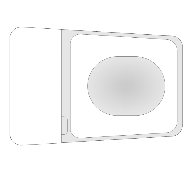
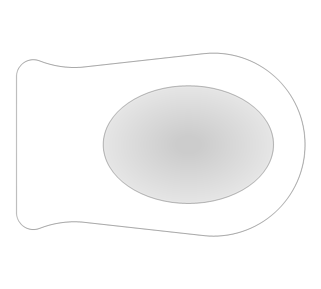
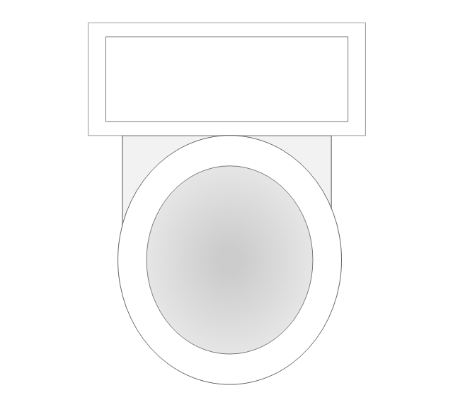
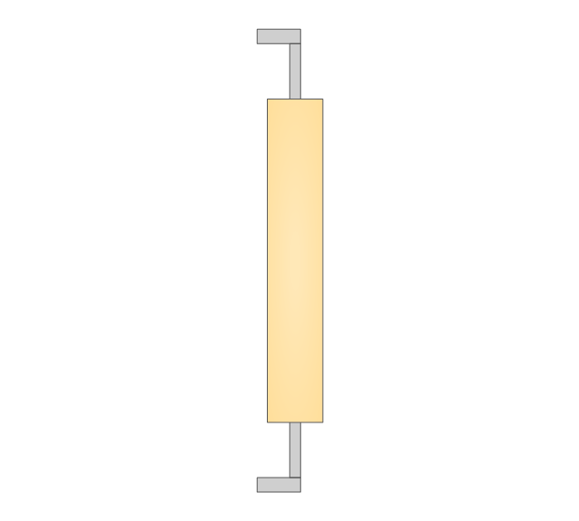
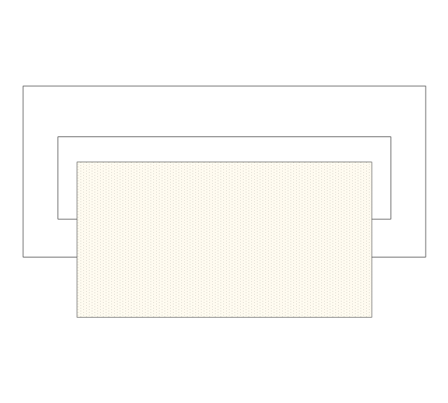
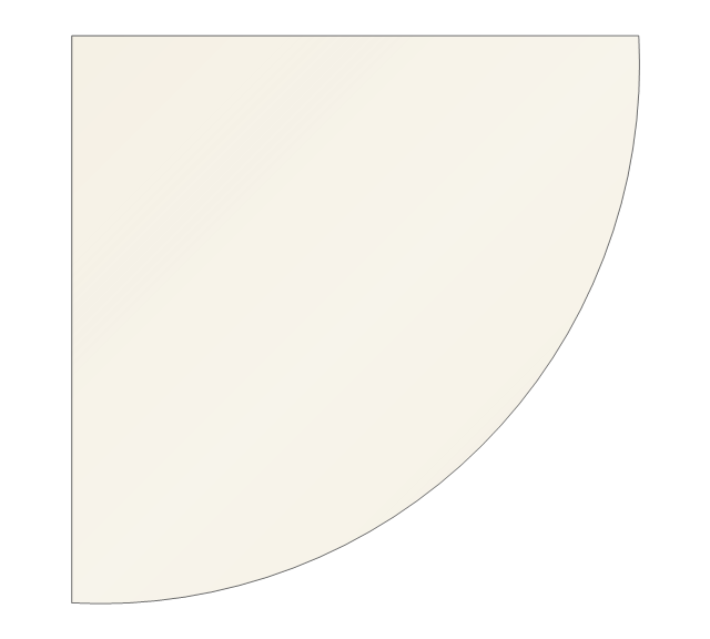
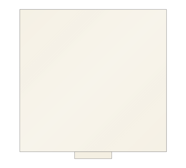
The vector stencils library "Bathroom" contains 41 bathroom equipment shapes. Use it for drawing bathroom layout plans: bathtubs, toilets, faucets, sinks, showers, bathroom furniture the ConceptDraw PRO diagramming and vector drawing software extended with the Floor Plans solution from the Building Plans area of ConceptDraw Solution Park.
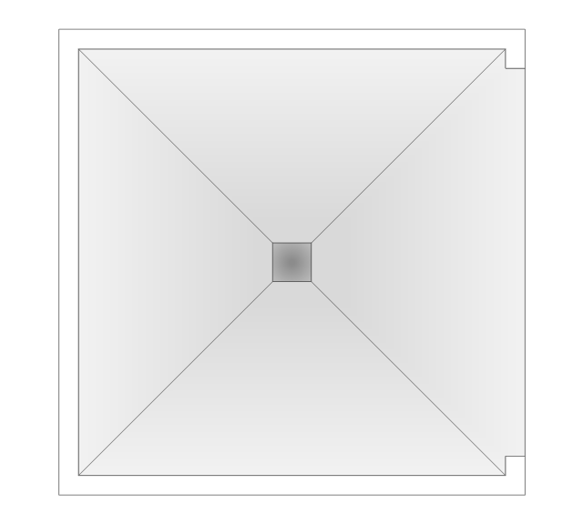
Shower
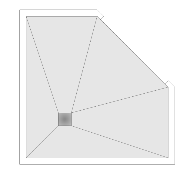
Corner Shower
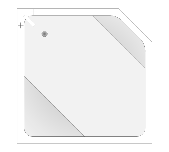
Corner Bath
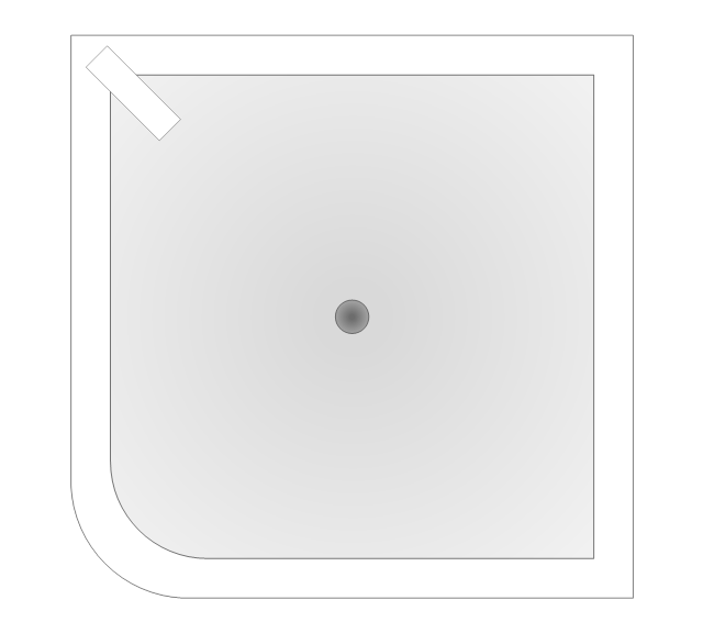
Square Tub
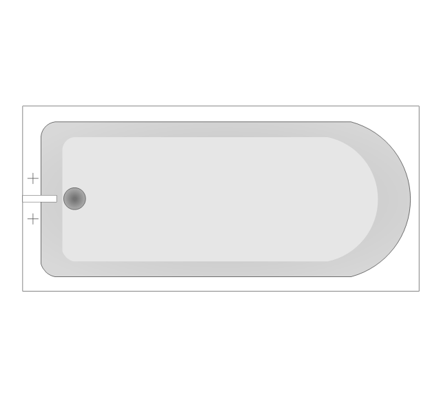
Bath Tub
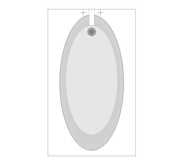
Bath 1
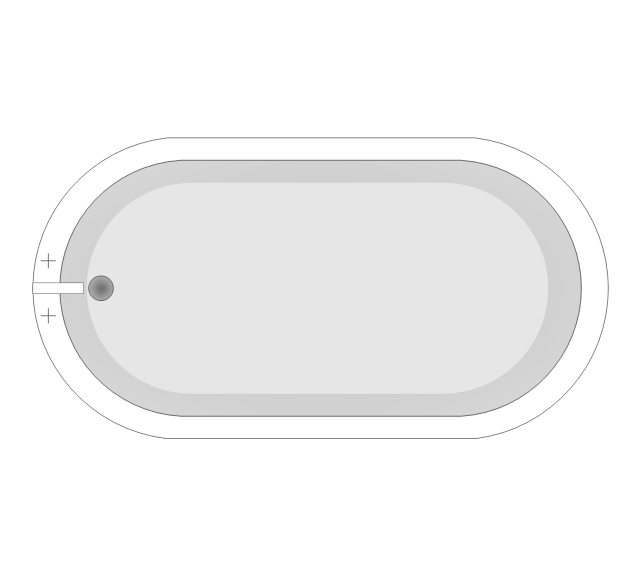
Bath 2
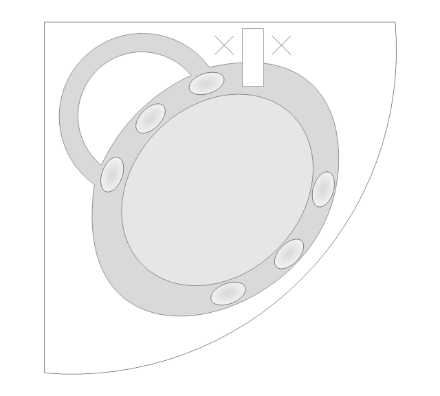
Spa Tub
Bidet
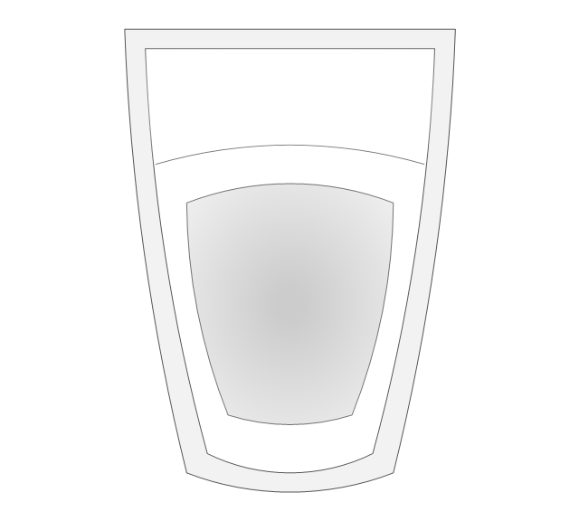
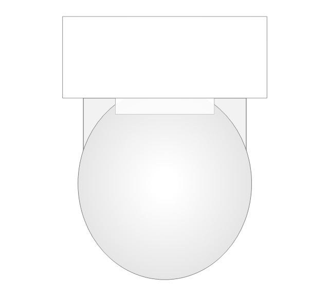
Wall Toilet
Toilet 1
Toilet 2
Toilet 3
Squat WC
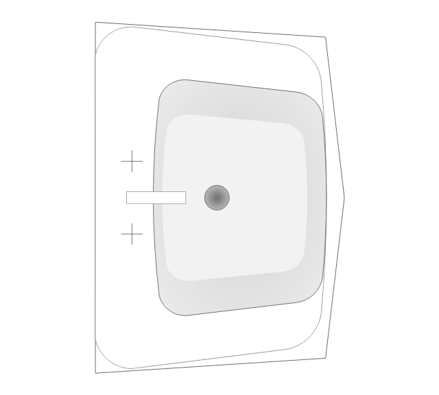
Pedestal Sink 1 (Oval)
-bathroom---vector-stencils-library.png--diagram-flowchart-example.png)
Pedestal Sink 2 (Oval)
-bathroom---vector-stencils-library.png--diagram-flowchart-example.png)
Pedestal Sink 3

Pedestal Sink 4
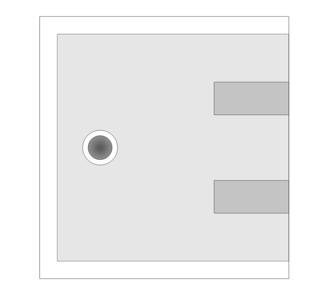
Countertop Sink
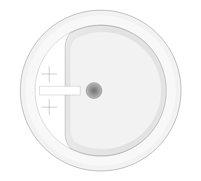
Round Sink

Vanity Sink

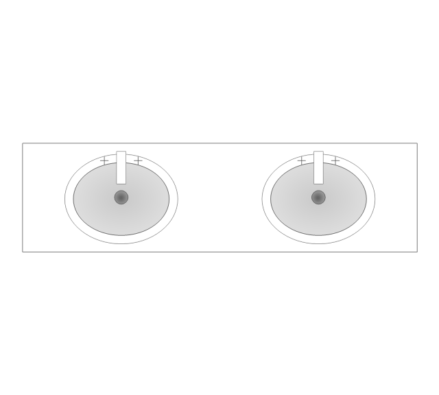
Double Vanity Sinks
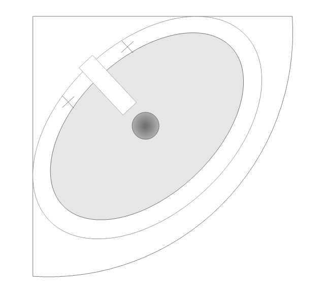
Corner Sink
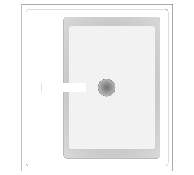
Basin
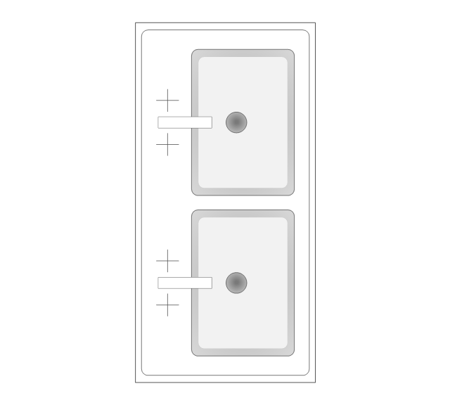
Double Basin
Towel Rack

Towel Rack with Towel
Toilet Paper Holder
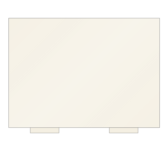
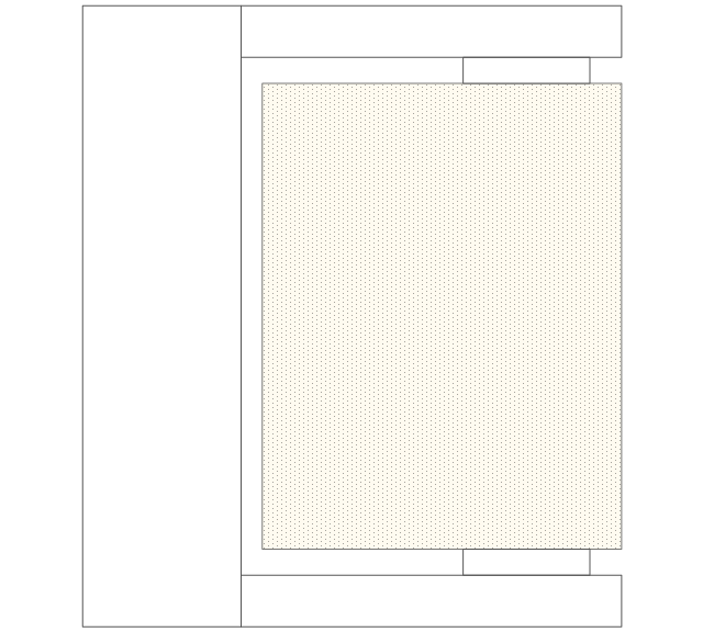
Countertop

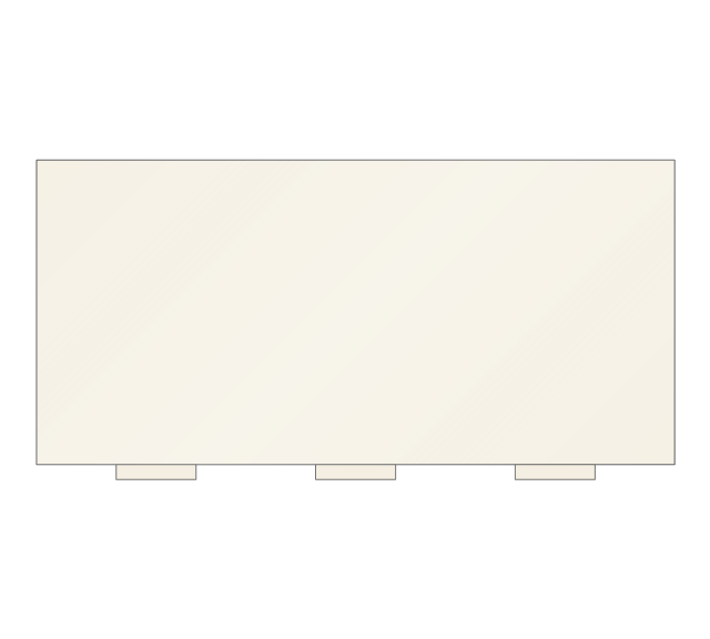
Corner Counter
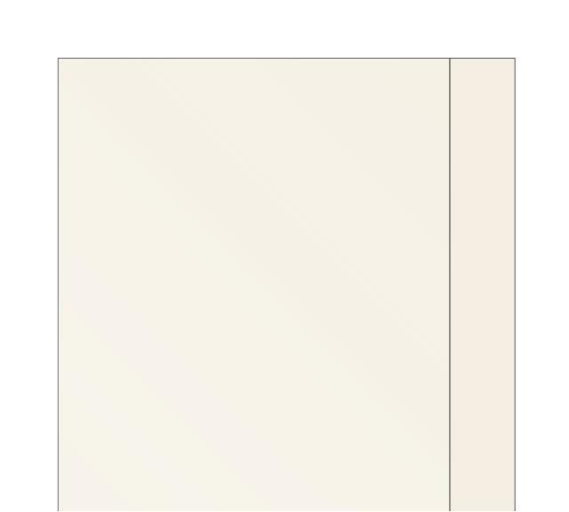
Cabinet 1
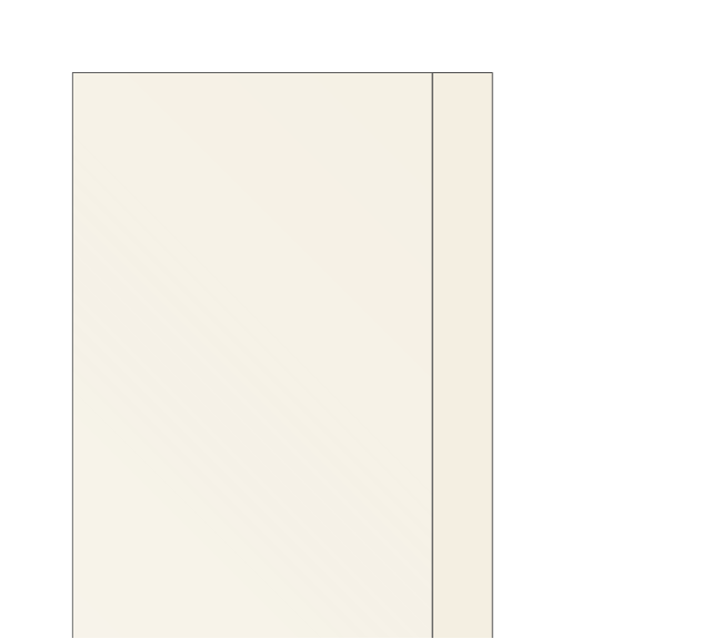
Cabinet 2
Cabinet 3
Medicine Cabinet 1
Medicine Cabinet 2
TP Dispenser
Hamper

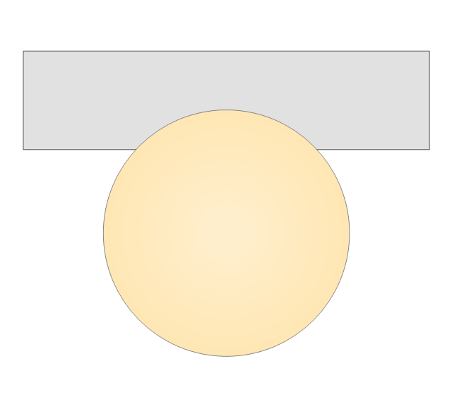
Single Light
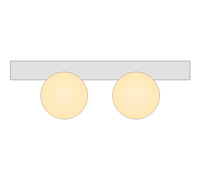
Double Light
3 Light Bar

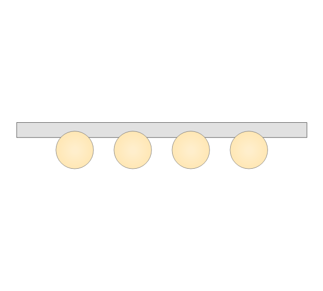
4 Light Bar
Wiring Diagrams with ConceptDraw PRO

- Wc Top View Png
- Wc Png Top View
- Squat Wc Png Top View
- Bathroom Furniture Png Top View
- Counter Top Wash Basin Top View Png
- Bathroom Sink Top View Png
- Bathroom - Vector stencils library | Freestanding Bath Plan View
- Top View Bath Vector
- Sink Top View Vector Draw
- Top View Of Building Vectors Png
- Washbasin Png Plan
- Baseball Diagram – Baseball Field – Corner View – Sample ...
- Building Services Sketches Wc Wash Basin Bathtub
- Cabinet Top View Png
- Plan Drawing Of Counter Top Sink
- Rec Tangular Glass Top View
- DroidDia prime | ERD Symbols and Meanings | Data Flow Diagrams ...
- Wc
- Bathroom - Vector stencils library | Restaurant water supply ...
- Bathroom - Vector stencils library | Design elements - Bathroom ...