The vector stencils library "HVAC ductwork" contains 55 duct and vent symbols of HVAC mechanical components. Use it for drawing HVAC ductwork system diagrams, heating, ventilation, air conditioning, refrigeration, automated building control, and environmental control design in the ConceptDraw PRO diagramming and vector drawing software extended with the HVAC Plans solution from the Building Plans area of ConceptDraw Solution Park.
Rect. duct, closed ends

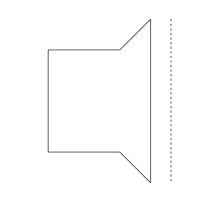
Rect. duct, open 1 end

Rect. duct, open both ends

Circ. duct, closed ends

Circ. duct, open 1 end

Circ. duct, open both ends

Branch duct, rectangular

Branch duct, circular

Variable bend

Miter bend

Y junction

3 way junction

Junction 1

Beveled junction, rect. duct, rect. branch

Beveled junction, rect. duct, circ. branch

Beveled junction, circ. duct, rect. branch

Beveled junction, circ. duct, circ. branch

Transition, rect. to rect.

Transition, rect. to circ.

Transition, circ. to rect.

Transition, circ. to circ.

Offset transition, rect. to rect.

Offset transition, rect. to circ.

Offset transition, circ. to rect.

Offset transition, circ. to circ.

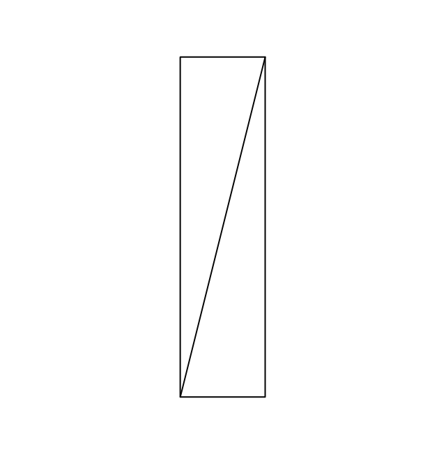
Flexible connection, rect. duct

Flexible connection, circ. duct

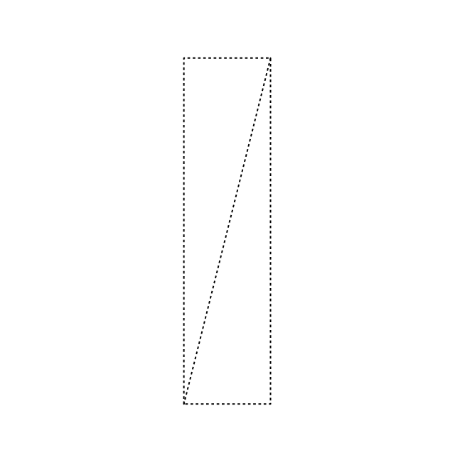
Flexible connection 2, rect. duct

Flexible connection 2, circ. duct

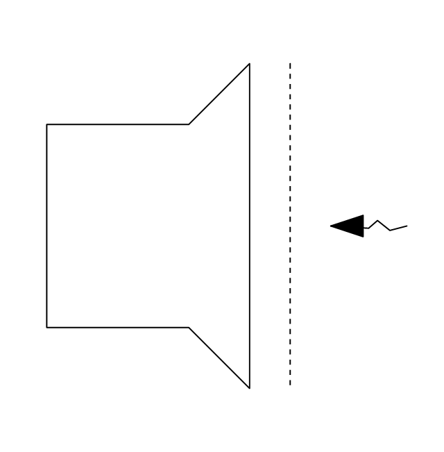
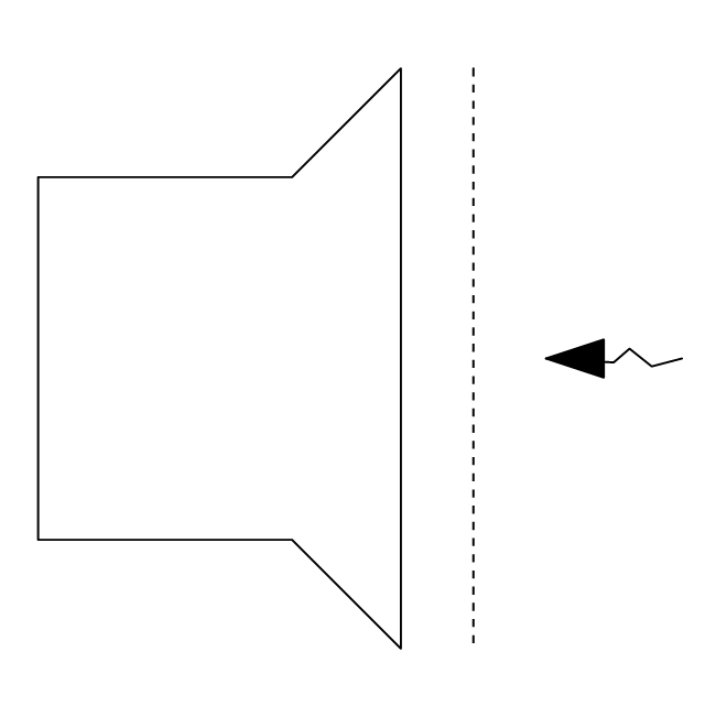
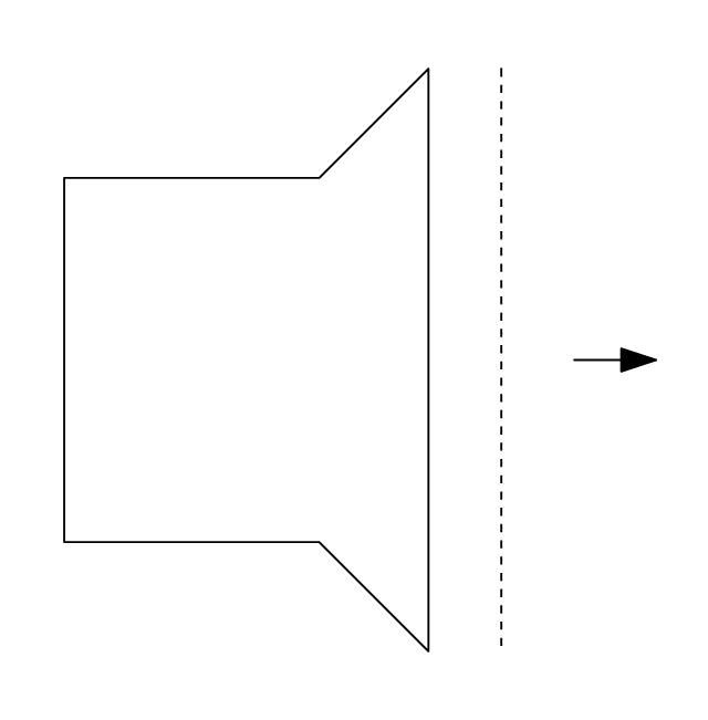
Supply, rect. duct toward

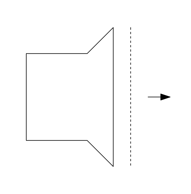
Supply, rect. duct away

Supply, rect. duct, elbow away

Supply, circ. duct toward

Supply, circ. duct away

Supply, circ. duct, elbow away

Return, rect. duct toward

Return, rect. duct away

Return, rect. duct, elbow away

Return, circ. duct toward

Return, circ. duct away

Return, circ. duct, elbow away

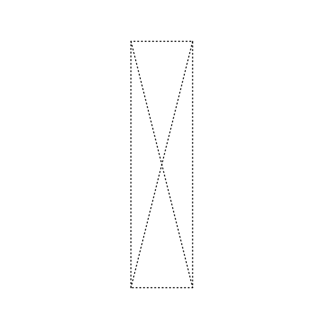
Sliding damper, rect. duct

Sliding damper, circ. duct

Damper, ACD

Damper, BD

Damper, FD/AD

Damper, MD

Damper, SD/AD

Vert. duct, rect. duct toward

Vert. duct, rect. duct away

Vert. duct, rect. duct, elbow away

Vert. duct, circ. duct toward

Vert. duct, circ. duct away

Vert. duct, circ. duct, elbow away

VAV box

The vector stencils library "HVAC control equipment" contains 48 HVAC symbols. Use it for drawing HVAC systems diagrams, heating, ventilation, air conditioning, refrigeration, automated building control, and environmental control design building plans and equipment layouts. The symbols example "HVAC control equipment - Vector stencils library" was created using the ConceptDraw PRO diagramming and vector drawing software extended with the HVAC Plans solution from the Building Plans area of ConceptDraw Solution Park.
Duct, sgl line

Duct, dbl line

Return duct, sgl line

Return duct, dbl line

Supply duct, sgl line

Supply duct, dbl line

Return duct 2, sgl line

Return duct 2, dbl line

Supply duct extension, sgl line

Supply duct extension, dbl line

Return duct extension, sgl line

Return duct extension, dbl line

2-fan section, sgl line

2-fan section, dbl line

3-fan section, sgl line

3-fan section, dbl line

4-fan section, sgl line

4-fan section, dbl line

VAV box

DD-VAV box

Fan coil housing

Unit heater

Centrifugal fan

Propeller fan

Vane axial fan

Damper

Filter

Air flow station

Humidifier

Htg/clg coil

Valve

Water flow meter

Pump


Cooling tower

Converter

Heat exchanger

Boiler

Equipment

Starter

VSD

Side to bottom pipe

Side to bottom pipe, arrow
Side to side pipe

Side to side pipe, arrow
Top to bottom pipe

Top to bottom pipe, arrow
Pipe flow arrow
The vector stencil library "HVAC ductwork" contains 63 duct and vent symbols.
Use it for drawing HVAC system diagrams, heating, ventilation, air conditioning, refrigeration, automated building control, and environmental control design floor
plans and equipment layouts.
"Ducts are used in heating, ventilation, and air conditioning (HVAC) to deliver and remove air. These needed airflows include, for example, supply air, return air, and exhaust air. Ducts also deliver, most commonly as part of the supply air, ventilation air. As such, air ducts are one method of ensuring acceptable indoor air quality as well as thermal comfort.
A duct system is often called ductwork. Planning ('laying out'), sizing, optimizing, detailing, and finding the pressure losses through a duct system is called duct design." [Duct (HVAC). Wikipedia]
The vector stencils example "Design elements - HVAC ductwork" is included in HVAC Plans solution from the Building Plans area of ConceptDraw Solution Park.
HVAC ductwork symbols

The vector stencils library "Pipes 1" contains 28 symbols of pipes. Use it for drawing plumbing and piping building plans, schematic diagrams, blueprints, or technical drawings of waste water disposal systems, hot and cold water supply systems in the ConceptDraw PRO diagramming and vector drawing software extended with the Plumbing and Piping Plans solution from the Building Plans area of ConceptDraw Solution Park.
General joint
Butt weld
Soldered / solvent
Screwed joint
Socket and spigot
Sleeve joint
Socket weld
Flanged / bolted

Swivel joint
Electrically bonded
Electrically insulated
End caps 1
End caps 2
End caps 3
Strainer

Separator
Exhaust silencer
Drain silencer
Open vent
Syphon drain
Hydrant
Tundish
Bell mouth
Exhaust head
Bursting disc
Flame arrester
Y strainer
Liquid seal open/closed
The vector stencils library "HVAC ductwork" contains 55 duct and vent symbols of HVAC mechanical components. Use it for drawing HVAC ductwork system diagrams, heating, ventilation, air conditioning, refrigeration, automated building control, and environmental control design in the ConceptDraw PRO diagramming and vector drawing software extended with the HVAC Plans solution from the Building Plans area of ConceptDraw Solution Park.
Rect. duct, closed ends
Rect. duct, open 1 end
Rect. duct, open both ends
Circ. duct, closed ends
Circ. duct, open 1 end
Circ. duct, open both ends
Branch duct, rectangular
Branch duct, circular
Variable bend
Miter bend
Y junction
3 way junction
Junction 1
Beveled junction, rect. duct, rect. branch
Beveled junction, rect. duct, circ. branch
Beveled junction, circ. duct, rect. branch
Beveled junction, circ. duct, circ. branch
Transition, rect. to rect.
Transition, rect. to circ.
Transition, circ. to rect.
Transition, circ. to circ.
Offset transition, rect. to rect.
Offset transition, rect. to circ.
Offset transition, circ. to rect.
Offset transition, circ. to circ.
Flexible connection, rect. duct
Flexible connection, circ. duct
Flexible connection 2, rect. duct
Flexible connection 2, circ. duct
Supply, rect. duct toward
Supply, rect. duct away
Supply, rect. duct, elbow away
Supply, circ. duct toward
Supply, circ. duct away
Supply, circ. duct, elbow away
Return, rect. duct toward
Return, rect. duct away
Return, rect. duct, elbow away
Return, circ. duct toward
Return, circ. duct away
Return, circ. duct, elbow away
Sliding damper, rect. duct
Sliding damper, circ. duct
Damper, ACD
Damper, BD
Damper, FD/AD
Damper, MD
Damper, SD/AD
Vert. duct, rect. duct toward
Vert. duct, rect. duct away
Vert. duct, rect. duct, elbow away
Vert. duct, circ. duct toward
Vert. duct, circ. duct away
Vert. duct, circ. duct, elbow away
VAV box
This HVAC floor plan sample shows the ventilation duct system layout.
"Ducts are used in heating, ventilation, and air conditioning (HVAC) to deliver and remove air. The needed airflows include, for example, supply air, return air, and exhaust air. Ducts commonly also deliver ventilation air as part of the supply air. As such, air ducts are one method of ensuring acceptable indoor air quality as well as thermal comfort.
A duct system is also called ductwork. Planning (laying out), sizing, optimizing, detailing, and finding the pressure losses through a duct system is called duct design." [Duct (flow). Wikipedia]
The HVAC floor plan example "Ductwork layout" was created using the ConceptDraw DIAGRAM diagramming and vector drawing software extended with the HVAC Plans solution from the Building Plans area of ConceptDraw Solution Park.
HVAC floor plan

The vector stencils library "Registers, drills and diffusers" contains 47 shapes of rectangular, circular, linear and troffer air handling inlet/ outlet components, registers, drills and diffusers. Use it for drawing reflected ceiling plans and HVAC plans in the ConceptDraw PRO diagramming and vector drawing software extended with the Reflected Ceiling Plans solution from the Building Plans area of ConceptDraw Solution Park.
Rectangular inlet
Rectangular inlet, hidden
Rectangular inlet, flow arrow
Rectangular inlet, flow arrow, hidden
Circular inlet
Circular inlet, hidden
Circular inlet, flow arrow
Circular inlet, flow arrow, hidden
Rectangular outlet
Rectangular outlet, hidden
Rectangular outlet, flow arrows
Rectangular outlet, flow arrows, hidden
Circular outlet
Circular outlet, hidden
Circular outlet, flow arrows
Circular outlet, flow arrows, hidden
Grille diffuser, rectangular duct
Grille diffuser, circular duct

Return grille diffuser, rectangular duct
Return grille diffuser, circular duct
Supply grille diffuser, rectangular duct
Supply grille diffuser, circular duct
Linear return diffuser
Linear return diffuser, hidden
Linear supply diffuser

Linear supply diffuser, hidden
Linear return diffuser, flow arrows
Linear return diffuser, flow arrows, hidden
Linear supply diffuser, flow arrows
Linear supply diffuser, flow arrows, hidden
Troffer inlet / outlet
Troffer inlet / outlet, hidden
Troffer inlet, return diffuser
Troffer inlet, return diffuser, hidden
Troffer inlet, supply diffuser
Troffer inlet, supply diffuser, hidden
Troffer outlet, return diffuser
Troffer outlet, return diffuser, hidden
Troffer outlet, supply diffuser
Troffer outlet, supply diffuser, hidden
Circular outlet
Circular outlet, hidden
Grille
Grille, hidden
Grille (side)
-registers,-drills-and-diffusers---vector-stencils-library.png--diagram-flowchart-example.png)
Grille (side), return diffuser
,-return-diffuser-registers,-drills-and-diffusers---vector-stencils-library.png--diagram-flowchart-example.png)
Grille (side), supply diffuser
,-supply-diffuser-registers,-drills-and-diffusers---vector-stencils-library.png--diagram-flowchart-example.png)
This mechanical room HVAC plan sample shows the layout of air handler (air handling unit, AHU) equipment: mixing chamber, air filter, fan (blower), heat exchanger coil, diffusers.
"Ventilating (the V in HVAC) is the process of "changing" or replacing air in any space to provide high indoor air quality (i.e. to control temperature, replenish oxygen, or remove moisture, odors, smoke, heat, dust, airborne bacteria, and carbon dioxide). Ventilation is used to remove unpleasant smells and excessive moisture, introduce outside air, to keep interior building air circulating, and to prevent stagnation of the interior air.
Ventilation includes both the exchange of air to the outside as well as circulation of air within the building. It is one of the most important factors for maintaining acceptable indoor air quality in buildings. Methods for ventilating a building may be divided into mechanical/ forced and natural types.
"Mechanical" or "forced" ventilation is used to control indoor air quality. Excess humidity, odors, and contaminants can often be controlled via dilution or replacement with outside air. However, in humid climates much energy is required to remove excess moisture from ventilation air.
Ventilation increases the energy needed for heating or cooling, however heat recovery ventilation can be used to mitigate the energy consumption. This involves heat exchange between incoming and outgoing air. Energy recovery ventilation additionally includes exchange of humidity." [Ventilation (architecture). Wikipedia]
The HVAC floor plan example "Ventilation system layout" was created using the ConceptDraw DIAGRAM diagramming and vector drawing software extended with the HVAC Plans solution from the Building Plans area of ConceptDraw Solution Park.
HVAC floor plan

Plumbing Plan

The vector stencils library "Registers, drills and diffusers" contains 47 shapes of rectangular, circular, linear and troffer air handling inlet/ outlet components, registers, drills and diffusers. Use it for drawing reflected ceiling plans and HVAC plans in the ConceptDraw PRO diagramming and vector drawing software extended with the Reflected Ceiling Plans solution from the Building Plans area of ConceptDraw Solution Park.
Rectangular inlet
Rectangular inlet, hidden
Rectangular inlet, flow arrow
Rectangular inlet, flow arrow, hidden
Circular inlet
Circular inlet, hidden
Circular inlet, flow arrow
Circular inlet, flow arrow, hidden
Rectangular outlet
Rectangular outlet, hidden
Rectangular outlet, flow arrows
Rectangular outlet, flow arrows, hidden
Circular outlet
Circular outlet, hidden
Circular outlet, flow arrows
Circular outlet, flow arrows, hidden
Grille diffuser, rectangular duct
Grille diffuser, circular duct
Return grille diffuser, rectangular duct
Return grille diffuser, circular duct
Supply grille diffuser, rectangular duct
Supply grille diffuser, circular duct
Linear return diffuser
Linear return diffuser, hidden
Linear supply diffuser
Linear supply diffuser, hidden
Linear return diffuser, flow arrows
Linear return diffuser, flow arrows, hidden
Linear supply diffuser, flow arrows
Linear supply diffuser, flow arrows, hidden
Troffer inlet / outlet
Troffer inlet / outlet, hidden
Troffer inlet, return diffuser
Troffer inlet, return diffuser, hidden
Troffer inlet, supply diffuser
Troffer inlet, supply diffuser, hidden
Troffer outlet, return diffuser
Troffer outlet, return diffuser, hidden
Troffer outlet, supply diffuser
Troffer outlet, supply diffuser, hidden
Circular outlet
Circular outlet, hidden
Grille
Grille, hidden
Grille (side)
Grille (side), return diffuser
Grille (side), supply diffuser
This HVAC schematics sample depicts the house cool mode of central air pool heater. It was drawn on the base of the HVAC schematics in the post "Central Air Pool Heater" from the Nathan Stratton's blog.
"With House Cool Mode, hot gas leaves the compressor runs through the reversing value into the condenser where it condenses into a liquid. Valve #1 is ON so liquid is able to leave the outside unit and run through the filter dryer and site glass into the evaporator upstairs in the house where the liquid flashes into a gas as it passes through the expansion valve and absorbs heat from the air passing through the evaporator. The cold gas travels downstairs and outside to the compressor and the cycle starts all over again." [robotics.net/ projects/ central-air-pool-heater/ ]
The HVAC schematics example "Central air pool heater" was created using the ConceptDraw DIAGRAM diagramming and vector drawing software extended with the HVAC Plans solution from the Building Plans area of ConceptDraw Solution Park.
HVAC schematics

The vector stencils library "Pipes 1" contains 28 symbols of pipes. Use it for drawing plumbing and piping building plans, schematic diagrams, blueprints, or technical drawings of waste water disposal systems, hot and cold water supply systems in the ConceptDraw PRO diagramming and vector drawing software extended with the Plumbing and Piping Plans solution from the Building Plans area of ConceptDraw Solution Park.
General joint
Butt weld
Soldered / solvent
Screwed joint
Socket and spigot
Sleeve joint
Socket weld
Flanged / bolted
Swivel joint
Electrically bonded
Electrically insulated
End caps 1
End caps 2
End caps 3
Strainer
Separator
Exhaust silencer
Drain silencer
Open vent
Syphon drain
Hydrant
Tundish
Bell mouth
Exhaust head
Bursting disc
Flame arrester
Y strainer
Liquid seal open/closed
 Plumbing and Piping Plans
Plumbing and Piping Plans solution extends ConceptDraw DIAGRAM software with samples, templates and libraries of pipes, plumbing, and valves design elements for developing of water and plumbing systems, and for drawing Plumbing plan, Piping plan, PVC Pipe plan, PVC Pipe furniture plan, Plumbing layout plan, Plumbing floor plan, Half pipe plans, Pipe bender plans.
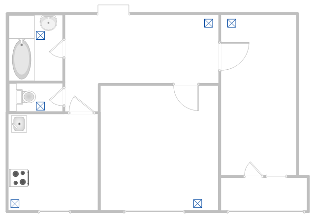
This apartment HVAC (Heating, Ventilating and Air Conditioning) plan shows the layout of exhaust ventilation duct outlet diffusers.
"Ventilation is the intentional introduction of outside air into a space. Ventilation is mainly used to control indoor air quality by diluting and displacing indoor pollutants; it can also be used for purposes of thermal comfort or dehumidification when the introduction of outside air will help to achieve desired indoor psychrometric conditions.
The intentional introduction of outside air can be categorized as either mechanical ventilation, or natural ventilation. Mechanical ventilation uses fans to drive the flow of outside air into a building. This may be accomplished by pressurization (in the case of positively pressurized buildings), or by depressurization (in the case of exhaust ventilation systems). Many mechanically ventilated buildings use a combination of both, with the ventilation being integrated into the HVAC system." [Ventilation (architecture). Wikipedia]
The floor plan example "Apartment HVAC plan" was created using the ConceptDraw DIAGRAM diagramming and vector drawing software extended with the HVAC Plans solution from the Building Plans area of ConceptDraw Solution Park.
Floor plan
The vector stencils library "HVAC equipment" contains 26 symbols of HVAC equipment. Use it for drawing HVAC system diagrams, heating, ventilation, air conditioning, refrigeration, automated building control and environmental control system layout floor plans in the ConceptDraw PRO diagramming and vector drawing software extended with the HVAC Plans solution from the Building Plans area of ConceptDraw Solution Park.
Rotary pump

Pump

Centrifugal pump

Fan blades, hor.

Fan blades, vert.

Fan blades, 4

Reciprocating pump

Screw pump

Centrifugal fan

Centrifugal fan 2

Axial fan

Axial fan 2

Moisture eliminator

Condenser

Condenser, plate type

Condenser, coil type

Air filter

Dryer

Silencer

Silencer 2

Pipe coil

Pipe coil, fins

Pipe coil, plate

Pipe coil, plate, fins

Refrigerant receiver

Chiller

The vector stencils library "Registers, drills and diffusers" contains 47 shapes of rectangular, circular, linear and troffer air handling inlet/ outlet components, registers, drills and diffusers. Use it for drawing reflected ceiling plans and HVAC plans in the ConceptDraw PRO diagramming and vector drawing software extended with the Reflected Ceiling Plans solution from the Building Plans area of ConceptDraw Solution Park.
Rectangular inlet
Rectangular inlet, hidden
Rectangular inlet, flow arrow
Rectangular inlet, flow arrow, hidden
Circular inlet
Circular inlet, hidden
Circular inlet, flow arrow
Circular inlet, flow arrow, hidden
Rectangular outlet
Rectangular outlet, hidden
Rectangular outlet, flow arrows
Rectangular outlet, flow arrows, hidden
Circular outlet
Circular outlet, hidden
Circular outlet, flow arrows
Circular outlet, flow arrows, hidden
Grille diffuser, rectangular duct
Grille diffuser, circular duct
Return grille diffuser, rectangular duct
Return grille diffuser, circular duct
Supply grille diffuser, rectangular duct
Supply grille diffuser, circular duct
Linear return diffuser
Linear return diffuser, hidden
Linear supply diffuser
Linear supply diffuser, hidden
Linear return diffuser, flow arrows
Linear return diffuser, flow arrows, hidden
Linear supply diffuser, flow arrows
Linear supply diffuser, flow arrows, hidden
Troffer inlet / outlet
Troffer inlet / outlet, hidden
Troffer inlet, return diffuser
Troffer inlet, return diffuser, hidden
Troffer inlet, supply diffuser
Troffer inlet, supply diffuser, hidden
Troffer outlet, return diffuser
Troffer outlet, return diffuser, hidden
Troffer outlet, supply diffuser
Troffer outlet, supply diffuser, hidden
Circular outlet
Circular outlet, hidden
Grille
Grille, hidden
Grille (side)
Grille (side), return diffuser
Grille (side), supply diffuser
The vector stencil library "HVAC equipment" contains 84 HVAC equipment symbols as pumps, fans, condensers, pipe coils, silencers, etc.
Use it for drawing HVAC system diagrams, heating, ventilation, air conditioning, refrigeration, automated building control, and environmental control design floor
plans and equipment layouts.
"HVAC (heating, ventilation, and air conditioning) is the technology of indoor and vehicular environmental comfort. HVAC system design is a subdiscipline of mechanical engineering, based on the principles of thermodynamics, fluid mechanics, and heat transfer. Refrigeration is sometimes added to the field's abbreviation as HVAC&R or HVACR, or ventilating is dropped as in HACR (such as the designation of HACR-rated circuit breakers).
HVAC is important in the design of medium to large industrial and office buildings such as skyscrapers and in marine environments such as aquariums, where safe and healthy building conditions are regulated with respect to temperature and humidity, using fresh air from outdoors." [HVAC. Wikipedia]
The vector stencils example "Design elements - HVAC equipment" is included in HVAC Plans solution from the Building Plans area of ConceptDraw Solution Park.
HVAC equipment symbols

This HVAC schematics sample depicts the house cool mode of central air pool heater. It was drawn on the base of the HVAC schematics in the post "Central Air Pool Heater" from the Nathan Stratton's blog.
"With House Cool Mode, hot gas leaves the compressor runs through the reversing value into the condenser where it condenses into a liquid. Valve #1 is ON so liquid is able to leave the outside unit and run through the filter dryer and site glass into the evaporator upstairs in the house where the liquid flashes into a gas as it passes through the expansion valve and absorbs heat from the air passing through the evaporator. The cold gas travels downstairs and outside to the compressor and the cycle starts all over again." [robotics.net/ projects/ central-air-pool-heater/ ]
The HVAC schematics example "Central air pool heater" was created using the ConceptDraw DIAGRAM diagramming and vector drawing software extended with the HVAC Plans solution from the Building Plans area of ConceptDraw Solution Park.
"With House Cool Mode, hot gas leaves the compressor runs through the reversing value into the condenser where it condenses into a liquid. Valve #1 is ON so liquid is able to leave the outside unit and run through the filter dryer and site glass into the evaporator upstairs in the house where the liquid flashes into a gas as it passes through the expansion valve and absorbs heat from the air passing through the evaporator. The cold gas travels downstairs and outside to the compressor and the cycle starts all over again." [robotics.net/ projects/ central-air-pool-heater/ ]
The HVAC schematics example "Central air pool heater" was created using the ConceptDraw DIAGRAM diagramming and vector drawing software extended with the HVAC Plans solution from the Building Plans area of ConceptDraw Solution Park.
HVAC schematics
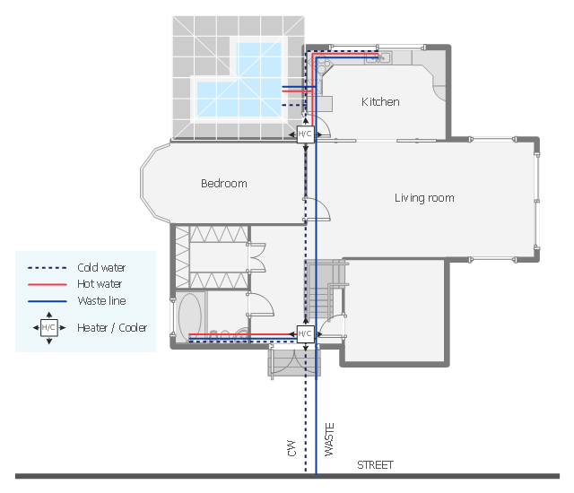
This plumbing and piping plan sample depicts the house hot and cold water supply and sanitation system.
"Within industry, piping is a system of pipes used to convey fluids (liquids and gases) from one location to another. The engineering discipline of piping design studies the efficient transport of fluid. ...
Plumbing is a piping system with which most people are familiar, as it constitutes the form of fluid transportation that is used to provide potable water and fuels to their homes and businesses. Plumbing pipes also remove waste in the form of sewage, and allow venting of sewage gases to the outdoors. Fire sprinkler systems also use piping, and may transport nonpotable or potable water, or other fire-suppression fluids." [Piping. Wikipedia]
The water supply and waste removal system scheme example "House plumbing plan" was created using the ConceptDraw PRO diagramming and vector drawing software extended with the Plumbing and Piping Plans solution from the Building Plans area of ConceptDraw Solution Park.
Plumbing and piping plan
 HVAC Plans
Use HVAC Plans solution to create professional, clear and vivid HVAC-systems design plans, which represent effectively your HVAC marketing plan ideas, develop plans for modern ventilation units, central air heaters, to display the refrigeration systems for automated buildings control, environmental control, and energy systems.
- Design elements - Pipes (part 1) | Drawing Symbol Of A Vent Pipe
- Plumbing Vent Size Chart
- Ductwork layout | Design elements | Hvac Duct Layout Drawing
- Design elements - HVAC ductwork | Ac Vent Duct Plans
- Design elements | Plumbing and Piping Plans | Air Vents Symbol Plan
- Design elements - HVAC ductwork | Plumbing and Piping Plans ...
- Design elements - HVAC ductwork | Mechanical Duct Symbols
- HVAC ductwork - Vector stencils library | Valves and fittings - Vector ...
- Ductwork layout | Design elements | Hvac Duct Design Example
- Design elements - HVAC ductwork | Vent Symbolic Diagram