Plumbing Plan
A plumbing plan is a technical drawing that shows the system of pipes and fixtures installed in a building to supply and distribute fresh water in it, also sewage disposal and removing waterborne wastes. It includes water supply lines, drains, valves, and fixtures. The water supply system includes cold water piping, hot water piping, and hot water return piping. The plumbing systems also include the systems of treating and purifying water taken from rivers, lakes, ponds, reservoirs, etc. The distribution system of pumps helps to pump and distribute water from the collection and purification facilities into storage tanks. It often includes pressure-stabilization devices.
The waste disposal system has two parts: the drainage system and the venting system. The drainage system consists of waste piping, soil piping, and vent piping. The venting system usually includes a number of pipes leading from waste pipes to the outdoors. Sanitary fixture traps are often used as a water seal. The detailed plumbing plan of a building may also include the plumbing fixture like washbasins, sinks, showers, toilets, bathtubs, lavatory basins, and appliances like hot-water heaters, washing machines, dishwashers, garbage-disposal units, drinking fountains, etc.
The plumbing equipment, water-carrying pipes, and other plumbing fixtures should be non-corrosive, durable, and strong to provide long life for the plumbing system. The most common materials for water pipes are copper, steel, brass, and plastic. Cast iron, steel, and copper are often used for sewage pipes. The pressure, corrosion factors, and other requirements are also considered when the plumbing system is planned. The plumbing systems codes and regulations are set and coordinated with building codes and should be adhered to. The pipes are installed into walls, floor, and ceiling obligatory according to the plan.
A well-planned schematic is essential for any modeling or remodeling project that involves plumbing work. The plumbing plan helps to minimize risks and avoid surprises during the installation of new plumbing equipment and reconstruction plumbing system, implement works accurately without affecting urban water cycle. The whole set of water supply drawings includes plumbing plans, riser diagrams, installation details, additional notes, and legends.
Detailed drawings are an essential part of architectural documentation, which is obligatory to receive all needed permits for construction and installation. They help to save time, avoid extra payments, generate a detailed plan of works, and calculate costs. Having an entire set of drawings, you can even spot something you might otherwise miss.
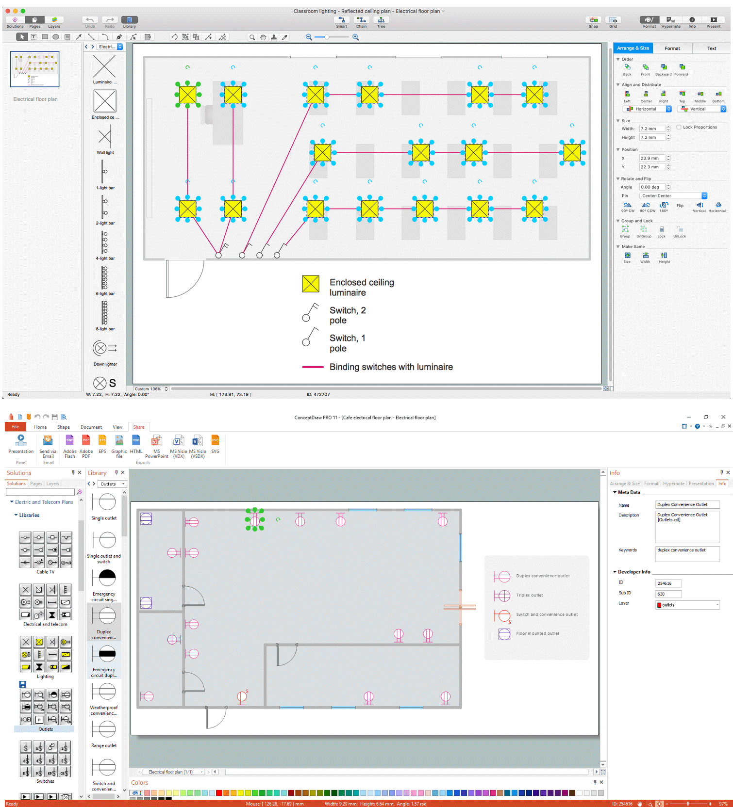
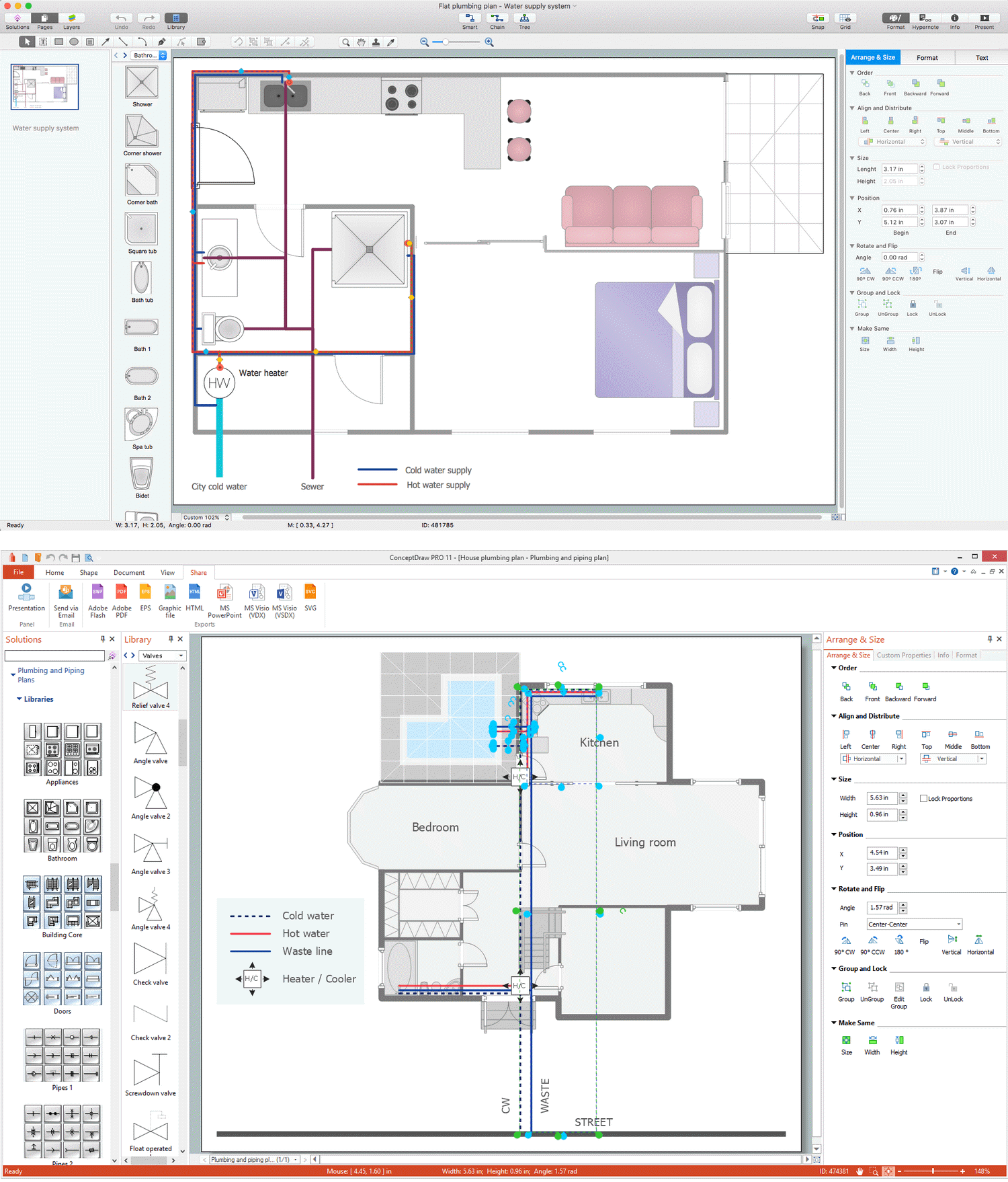
Example 1. Plumbing Plan
ConceptDraw DIAGRAM is an ideal software to create a plumbing plan, water supply system drawings, riser drawings, drainage system drawings, irrigation system drawings, storm water system drawings, and many more documentation materials. The variety of universally recognized plumbing symbols included in ConceptDraw DIAGRAM solutions libraries helps to illustrate the entire plumbing system and make your plans clear. The plans usually include pipes and fixture units, the pipes are marked with sizes. Different colors are used to identify pipes. The slope is indicated for drainage pipes; the capacity of pumps and other equipment and other details are also included.

Example 2. Water and Sewage Library Design Elements
Public Utilities solution helps to create varied infographics, diagrams, and illustrations related to the most important spheres of life support, including electrical and plumbing systems. This solution provides a large set of pre-made samples and 12 libraries with an enormous collection of vector design elements and graphics icons in public utilities area. Stay efficient in communication with customers and contractors with ConceptDraw DIAGRAM vector drawing and diagramming software.

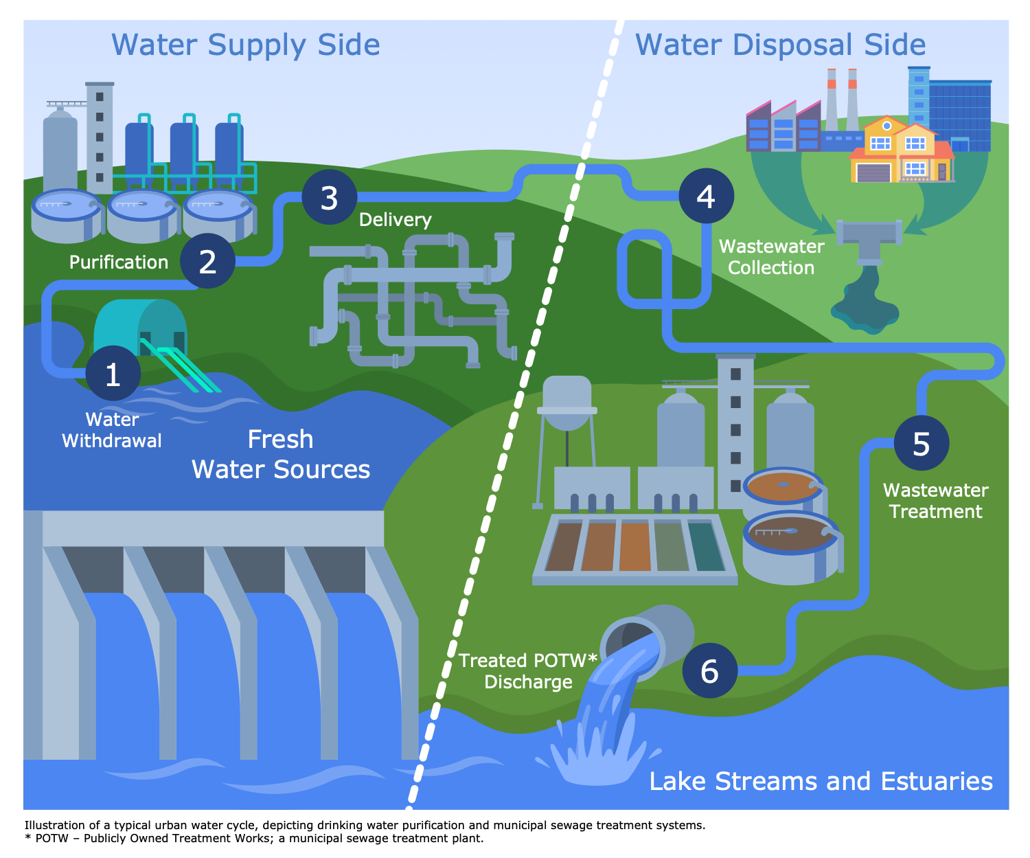
Example 3. Public Works - Water Supply
The Public Utilities Infographics samples you see on this page were created in ConceptDraw DIAGRAM software using the drawing tools of the Public Utilities Solution. These examples successfully demonstrate solution's capabilities and the professional results you can achieve using it. An experienced user spent 10-15 minutes creating each of these samples.
Use the powerful tools of the Public Utilities solution to design your own Public Utilities Infographics quick, easy, and effective.
All source documents are vector graphic documents. They are available for reviewing, modifying, or converting to a variety of formats (PDF file, MS PowerPoint, MS Visio, and many other graphic formats) from the ConceptDraw STORE. The Public Utilities Solution is available for ConceptDraw DIAGRAM users.