Use Case Diagrams technology with ConceptDraw PRO

Garrett IA Diagrams with ConceptDraw PRO

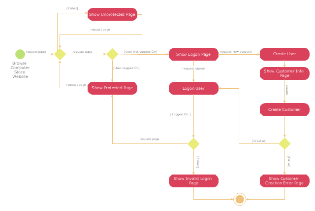
"A registered user is one who uses a program or a website and provides his/ her credentials, effectively proving his/ her identity. ...
Generally speaking, any person can become a registered user by providing some credentials, usually in the form of a username (or email) and password. After that, one can access information and privileges unavailable to non-registered users, usually referred to simply as guests. The action of providing the proper credentials for a website is called logging in, or signing in." [Registered user. Wikipedia]
The UML activity diagram example "User registration" was created using the ConceptDraw PRO diagramming and vector drawing software extended with the Rapid UML solution from the Software Development area of ConceptDraw Solution Park.
UML activity diagram
 Computer Network Diagrams
Computer Network Diagrams solution extends ConceptDraw PRO software with samples, templates and libraries of vector stencils for drawing the computer network topology diagrams.
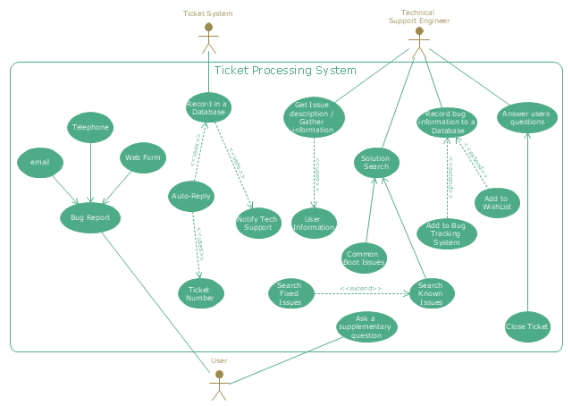
"An example scenario is presented to demonstrate how a common issue tracking system would work:
(1) A customer service technician receives a telephone call, email, or other communication from a customer about a problem. Some applications provide built-in messaging system and automatic error reporting from exception handling blocks.
(2) The technician verifies that the problem is real, and not just perceived. The technician will also ensure that enough information about the problem is obtained from the customer. This information generally includes the environment of the customer, when and how the issue occurs, and all other relevant circumstances.
(3) The technician creates the issue in the system, entering all relevant data, as provided by the customer.
(4) As work is done on that issue, the system is updated with new data by the technician. Any attempt at fixing the problem should be noted in the issue system. Ticket status most likely will be changed from open to pending.
(5) After the issue has been fully addressed, it is marked as resolved in the issue tracking system.
If the problem is not fully resolved, the ticket will be reopened once the technician receives new information from the customer. A Run Book Automation process that implements best practices for these workflows and increases IT personnel effectiveness is becoming very common." [Issue tracking system. Wikipedia]
The UML use case diagram example "Ticket processing system" was created using the ConceptDraw PRO diagramming and vector drawing software extended with the Rapid UML solution from the Software Development area of ConceptDraw Solution Park.
UML use case diagram
- UML activity diagram - User registration | Rapid UML | Diagramming ...
- UML use case diagram - Banking system
- UML Use Case Diagram Example Social Networking Sites Project ...
- Uml Diagram Company And User
- UML Use Case Diagram Example Registration System | UML activity ...
- Diagramming Software for Design UML Use Case Diagrams | UML ...
- Activity Diagram For User Login
- UML Use Case Diagram Example Registration System
- UML Class Diagram Generalization Example UML Diagrams | UML ...
- UML Use Case Diagram Example Registration System | Use Case ...
- UML activity diagram - User registration | UML Deployment Diagram ...
- UML activity diagram - User registration | Entity-Relationship ...
- UML Diagram | UML Use Case Diagram Example Social Networking ...
- UML sequence diagram - Help desk | UML Diagram of Parking ...
- User Activity Diagram
- UML Diagram | UML Use Case Diagrams | Diagramming Software ...
- UML Activity Diagram | UML activity diagram - User registration ...
- UML activity diagram - User registration | How to Install and Activate ...
- Flowchart | Wireframe Examples | Data Flow Diagrams | Dfd For ...
- UML activity diagram - User registration | Rapid UML | Software and ...