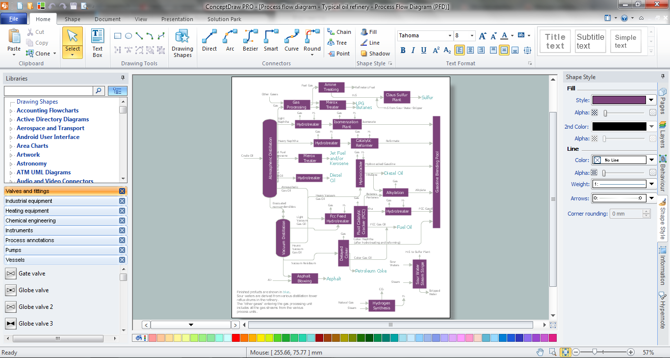
Process Flow Diagram Symbols

Process Flow Diagram

This process flow diagram (PFD) example shows an amine treating system for the removal of gaseous hydrogen sulfide from gas streams. It is used in oil refineries and chemical plants. This PFD sample was redesigned from the Wikimedia Commons file: AmineTreating.png. [commons.wikimedia.org/ wiki/ File:AmineTreating.png]
This file is licensed under the Creative Commons Attribution-Share Alike 3.0 Unported license. [creativecommons.org/ licenses/ by-sa/ 3.0/ deed.en]
"Amine gas treating, also known as gas sweetening and acid gas removal, refers to a group of processes that use aqueous solutions of various alkylamines (commonly referred to simply as amines) to remove hydrogen sulfide (H2S) and carbon dioxide (CO2) from gases. It is a common unit process used in refineries, and is also used in petrochemical plants, natural gas processing plants and other industries.
Processes within oil refineries or chemical processing plants that remove hydrogen sulfide are referred to as "sweetening" processes because the odor of the processed products is improved by the absence of hydrogen sulfide. An alternative to the use of amines involves membrane technology. Membranes are attractive since no reagents are consumed.
Many different amines are used in gas treating:
Diethanolamine (DEA),
Monoethanolamine (MEA),
Methyldiethanolamine (MDEA),
Diisopropanolamine (DIPA),
Aminoethoxyethanol (Diglycolamine) (DGA).
The most commonly used amines in industrial plants are the alkanolamines DEA, MEA, and MDEA. These amines are also used in many oil refineries to remove sour gases from liquid hydrocarbons such as liquified petroleum gas (LPG)." [Amine gas treating. Wikipedia]
The PFD example "Amine treating unit schematic diagram" was drawn using the ConceptDraw PRO diagramming and vector drawing software extended with the Chemical and Process Engineering solution from the Chemical and Process Engineering area of ConceptDraw Solution Park.
Process Flow Diagram (PFD)
-amine-treating-unit-schematic-diagram.png--diagram-flowchart-example.png)
Process Engineering
 Chemical and Process Engineering
This chemical engineering solution extends ConceptDraw DIAGRAM.9.5 (or later) with process flow diagram symbols, samples, process diagrams templates and libraries of design elements for creating process and instrumentation diagrams, block flow diagrams (BFD
Process and Instrumentation Diagram
Technical Drawing Software

- Oil And Gas Industry Process Flow Diagrams
- Design For Maintenance In Oil And Gas Industry Flowchart
- Mechanical Drawing Symbols | Directional control valve | Retract ...
- Schematic Diagram Of Different Types Of Valves
- Retract resistor check valve application | Directional control valve ...
- Different Types Of Valves And Their Uses
- Oil And Gas Industry Process Flow Diagram Symbol
- Oil And Gas Process Symbols
- Engineering | Material Requisition Flowchart. Flowchart Examples ...
- Crude oil distillation unit - PFD | Jet fuel mercaptan oxidation treating ...
- Fluid Power Examples
- Valve Types With Digram Procces In Oil Industry
- Sample Oil And Gas Process Flow Diagram In Pdf
- Oil And Gas Symbol
- Diagrams Of All Valves And Fittings Use In Chemical Engineering
- Chemical and Process Engineering | Valves and fittings - Vector ...
- Process Flowchart | Process Flow Diagram | Process Flow Chart ...
- Gravity filtration of liquids | Design elements - Pumps | Natural gas ...
- Percentage Pie Chart. Pie Chart Examples | EU greenhouse gas ...
- Pneumatic 4-ported 3-position valve template - Win | Mechanical ...