Diagramming Software for Design UML Activity Diagrams


UML Activity Diagram

UML Activity Diagram. Design Elements

The vector stencils library "UML activity diagrams" contains 37 symbols for the ConceptDraw PRO diagramming and vector drawing software.
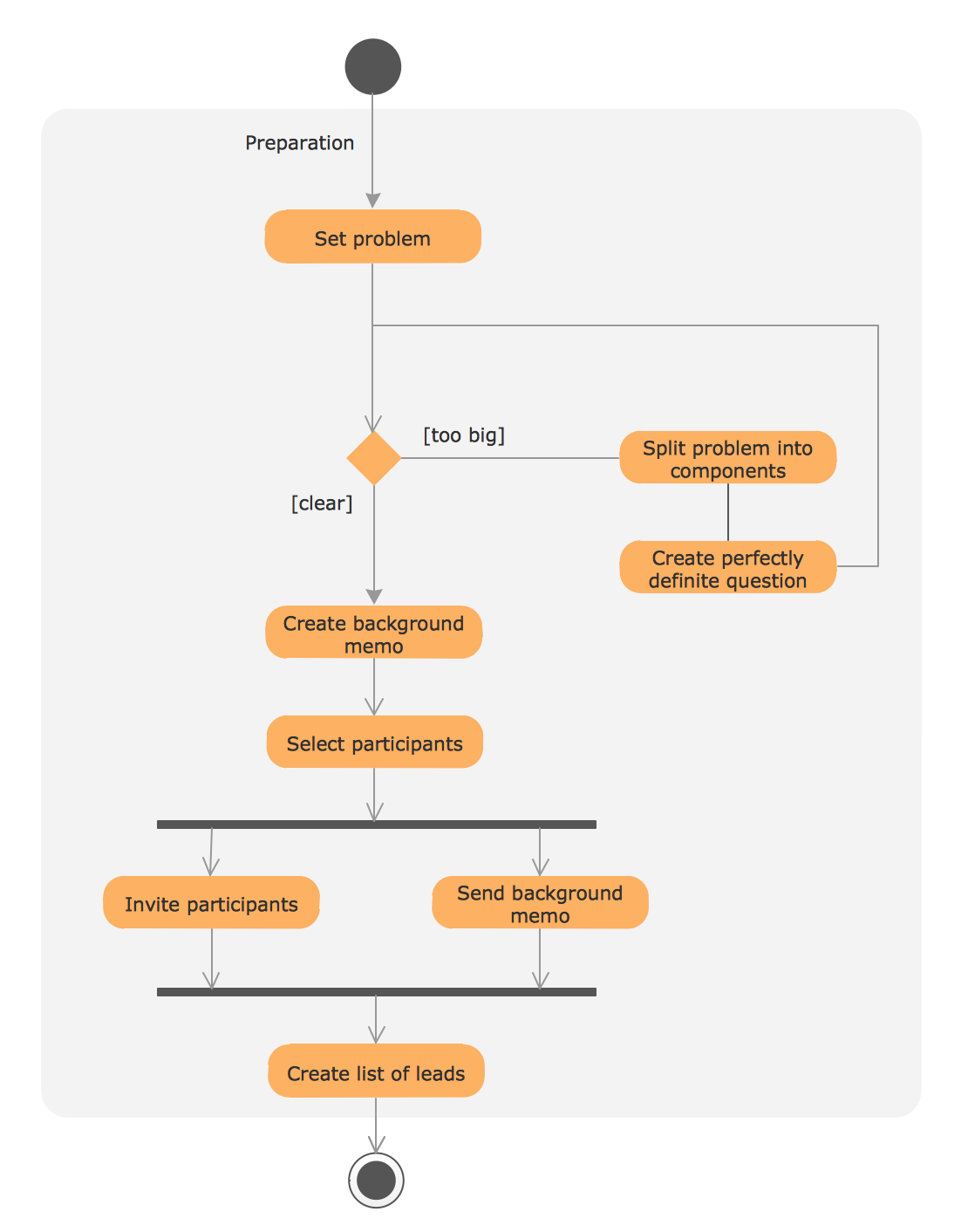
"Activity diagrams are constructed from a limited number of shapes, connected with arrows. The most important shape types:
(1) rounded rectangles represent actions;
(2) diamonds represent decisions;
(3) bars represent the start (split) or end (join) of concurrent activities;
(4) a black circle represents the start (initial state) of the workflow;
(5) an encircled black circle represents the end (final state).
Arrows run from the start towards the end and represent the order in which activities happen.
Hence they can be regarded as a form of flowchart. Typical flowchart techniques lack constructs for expressing concurrency. However, the join and split symbols in activity diagrams only resolve this for simple cases; the meaning of the model is not clear when they are arbitrarily combined with decisions or loops." [Activity diagram. Wikipedia]
The example "Design elements - UML activity diagrams" is included in the Rapid UML solution from the Software Development area of ConceptDraw Solution Park.
UML activity diagram symbols

UML Process Diagram Example
 Workflow Diagrams
Workflow Diagrams solution extends ConceptDraw DIAGRAM software with samples, templates and vector stencils library for drawing the work process flowcharts.
UML Flowchart Symbols

 Rapid UML
Rapid UML solution extends ConceptDraw DIAGRAM software with templates, samples and libraries of vector stencils for quick drawing the UML diagrams using Rapid Draw technology.
HelpDesk
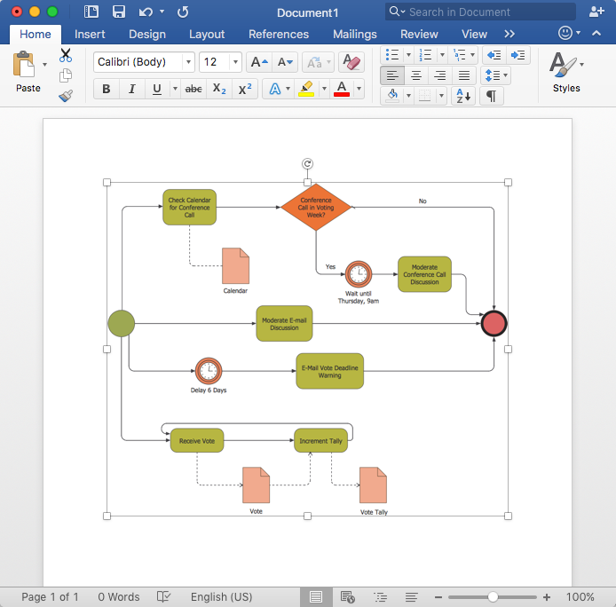
How to Add a Business Process Diagram to MS Word Document
HelpDesk
How to Create a Workflow Diagram Using ConceptDraw Solutions

UML Notation

 ATM UML Diagrams
The ATM UML Diagrams solution lets you create ATM solutions and UML examples. Use ConceptDraw DIAGRAM as a UML diagram creator to visualize a banking system.
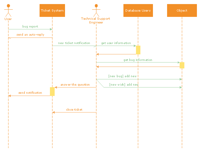
"An example scenario is presented to demonstrate how a common issue tracking system would work:
(1) A customer service technician receives a telephone call, email, or other communication from a customer about a problem. Some applications provide built-in messaging system and automatic error reporting from exception handling blocks.
(2) The technician verifies that the problem is real, and not just perceived. The technician will also ensure that enough information about the problem is obtained from the customer. This information generally includes the environment of the customer, when and how the issue occurs, and all other relevant circumstances.
(3) The technician creates the issue in the system, entering all relevant data, as provided by the customer.
(4) As work is done on that issue, the system is updated with new data by the technician. Any attempt at fixing the problem should be noted in the issue system. Ticket status most likely will be changed from open to pending.
(5) After the issue has been fully addressed, it is marked as resolved in the issue tracking system.
If the problem is not fully resolved, the ticket will be reopened once the technician receives new information from the customer. A Run Book Automation process that implements best practices for these workflows and increases IT personnel effectiveness is becoming very common." [Issue tracking system. Wikipedia]
The UML sequence diagram example "Ticket processing system" was created using the ConceptDraw PRO diagramming and vector drawing software extended with the Rapid UML solution from the Software Development area of ConceptDraw Solution Park.
UML sequence diagram
 Business Processes
Business Process solution extends ConceptDraw DIAGRAM software with business process diagrams as cross-functional flowcharts, workflows, process charts, IDEF0, timelines, calendars, Gantt charts, business process modeling, audit and opportunity flowcharts.
- UML Activity Diagram
- UML Activity Diagram
- UML Activity Diagram | Diagramming Software for Design UML ...
- UML Use Case Diagram Example - Taxi Service | Workflow ...
- Uml Activity Diagrams For C
- UML activity diagram - Template
- Diagramming Software for Design UML Activity Diagrams | UML ...
- Purchase order processing UML activity diagram | Event-driven ...
- UML Diagrams with ConceptDraw PRO | UML Business Process ...
- UML Activity Diagram | Diagramming Software for Design UML ...
- Best Program to Make Workflow Diagrams | UML Diagrams with ...
- How to Design a Good Workflow | UML Tool & UML Diagram ...
- Diagramming Software for Design UML Activity Diagrams | UML ...
- ATM UML Diagrams | Sales workflow - Vector stencils library | Rapid ...
- Workflow Diagram | UML activity diagram - Payment process ...
- Business Process Diagram | Workflow Diagrams | Rapid UML ...
- UML 2 4 Process Flow Diagram | Diagramming Software for Design ...
- UML State Machine Diagram.Design Elements | Workflow Diagram ...
- UML Use Case Diagram Example - Taxi Service | Workflow ...
- Workflow Diagram Software Mac | Diagramming Software for Design ...