This site uses cookies. By continuing to browse the ConceptDraw site you are agreeing to our Use of Site Cookies.

Complete Network Topology

This sample was created in ConceptDraw DIAGRAM diagramming and vector drawing software using the Computer and Networks solution from Computer and Networks area of ConceptDraw Solution Park.
A complete (fully connected) topology is a network topology in which there is a direct link between all pairs of nodes. In a fully connected network with n nodes, there are n(n-1)/2 direct links. Networks designed with this topology are usually very expensive to set up, but provide a high degree of reliability due to the multiple paths for data that are provided by the large number of redundant links between nodes.

Network Topologies

Running your own business or working for some company as IT specialist, one day you definitely face the need of connecting all network and computer devices existing on this enterprise's balance sheet. Especially once this company grows you need more stuff and so elements of network such as laptops, servers, scanners, printers, fax machines, telephones, routers, so you definitely have to make network topology flowchart to arrange it all correctly to connect it with each other. In this case to use ConceptDraw DIAGRAM as a tool to make your topology diagram is the best decision ever! Test how simple it is to use our samples to create your diagrams in a short term! Whether you need to make logical or physical topologies you can always use the service of our software and with help of libraries to design whatever you need. The basic topologies types are: ring, mesh, bus, star, tree or fully connected one, and its examples are there in Solutions waiting for you on this site to use it all. Check it out and enjoy simplicity of using this application right now!
Create Network Topology Diagram

OSPF Network. Computer and Network Examples

OSPF is an interior gateway protocol (IGP), it is widely used in large enterprise networks. OSPF routes the IP packets within a single routing domain. It gathers the information about the link state from the routers and makes the network topology map.
This example was created in ConceptDraw DIAGRAM using the Computer and Networks Area of ConceptDraw Solution Park and shows the OSPF diagram.

network layout, network floor plan, network visualization, network topologies, network topology mapper Network Layout Floor Plans

network layout, network floor plan, network visualization, network topologies, network topology mapper
Network Layout Floor Plans solution extends ConceptDraw DIAGRAM software functionality with powerful tools for quick and efficient documentation the network equipment and displaying its location on the professionally designed Network Layout Floor Plans. Never before creation of Network Layout Floor Plans, Network Communication Plans, Network Topologies Plans and Network Topology Maps was not so easy, convenient and fast as with predesigned templates, samples, examples and comprehensive set of vector design elements included to the Network Layout Floor Plans solution. All listed types of plans will be a good support for the future correct cabling and installation of network equipment.

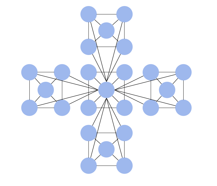
Hierarchical Network Topology

This sample was created in ConceptDraw DIAGRAM diagramming and vector drawing software using the Computer and Networks solution from Computer and Networks area of ConceptDraw Solution Park.
This sample shows the Hierarchical network topology.
A Hierarchical network topology interconnects multiple groups that are located on the separate layers to form a larger network. Each layer concentrates on the specified functions, this allows to choose the right equipment for the layer.

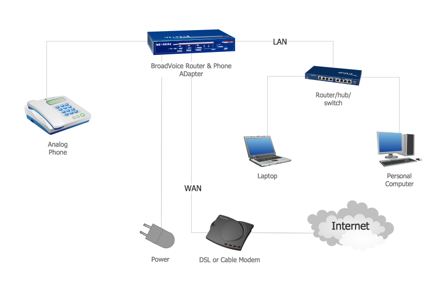
Network VOIP. Computer and Network Examples

Voice-over-Internet protocol (VoIP) is a protocol of the voice communications and multimedia sessions through the Internet or other packet-switched networks. VoIP systems use the data compression techniques, encapsulated in a data-packet stream over IP. They allows users to use regular telephone networks through any internet service provider and anywhere. VoIP is also called IP telephony, Internet telephony, Voice over broadband (VoBB).
This example was created in ConceptDraw DIAGRAM using the Computer and Networks Area of ConceptDraw Solution Park and shows the VoIP Network.

Hotel Network Topology Diagram

Hotel Network Topology Diagram - The Computer and Networks solution from Computer and Networks area of ConceptDraw Solution Park provides examples, templates and vector stencils library with symbols of local area network (LAN) and wireless LAN (WLAN) equipment.
Use it to draw the physical and logical network topology diagrams for wired and wireless computer communication networks.
Create Network Topology Diagram

Network Diagram Software Logical Network

ConceptDraw Network Diagram is ideal for network engineers and network designers who need to draw Logical Network diagrams.

Cisco networking, Cisco network icons, Cisco icon Cisco Network Diagrams

Cisco networking, Cisco network icons, Cisco icon
Cisco Network Diagrams solution extends ConceptDraw DIAGRAM with the best characteristics of network diagramming software. Included samples, templates and libraries of built-in standardized vector Cisco network icons and Cisco symbols of computers, network devices, network appliances and other Cisco network equipment will help network engineers, network designers, network and system administrators, as well as other IT professionals and corporate IT departments to diagram efficiently the network infrastructure, to visualize computer networks topologies, to design Cisco computer networks, and to create professional-looking Cisco Computer network diagrams, Cisco network designs and schematics, Network maps, and Network topology diagrams in minutes.

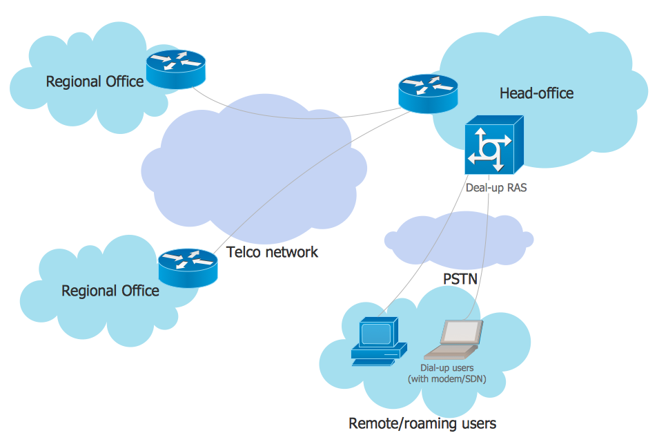
EPN Frame-Relay and Dial-up Network. Computer and Network Examples

An Enterprise private network (EPN) is a computer network built by an enterprise to interconnect the sites of the company (such as head and remote offices, shops, production sites, etc.) on purpose to share the computer resources.
This example was created in ConceptDraw DIAGRAM using the Computer and Networks solution from the Computer and Networks area of ConceptDraw Solution Park. It shows the Enterprise Private Network (EPN) using the frame-relay and dial-up.